


October 30, 2021
Operation steps of Launch X431 PAD 7 configuration online programming function:
Go to options:
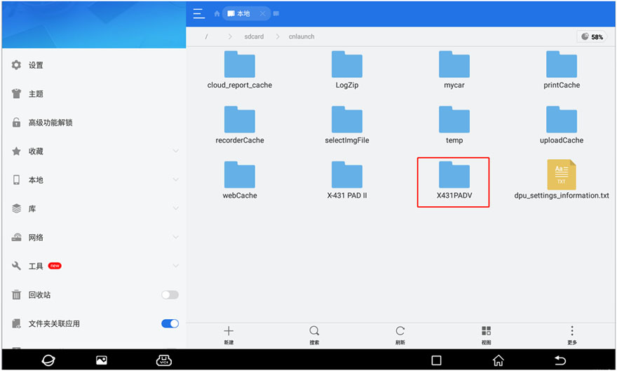
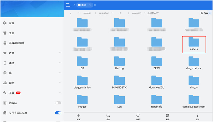
Other—Equipment—File Management—-cnlaunch folder—-X431PADV—assets directory, find the file named StdCfg.ini.
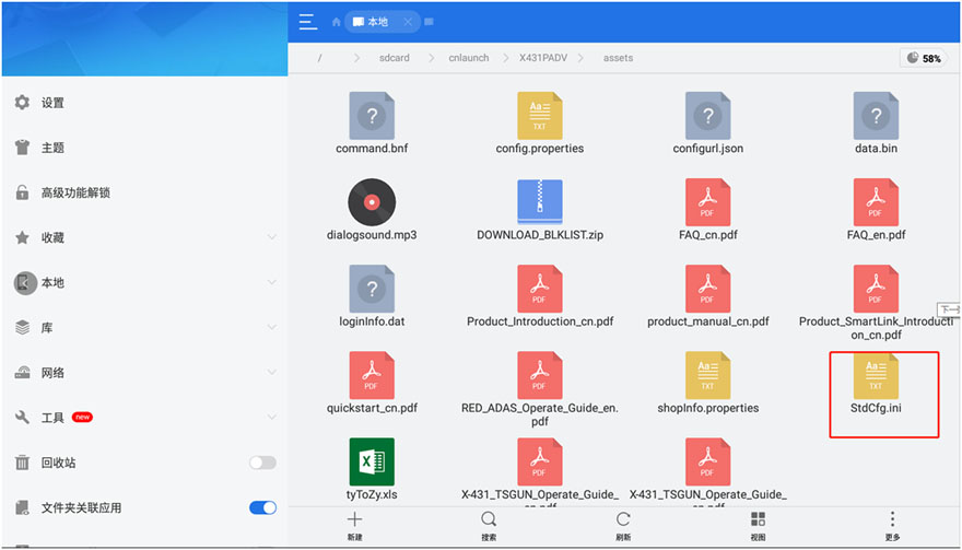
Open StdCfg.ini with a text editor and click the edit button on the upper right to make the file editable.
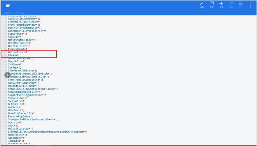
Find the two fields "OnlineFlash†and "Flashâ€, their default value is 0,
which means that the diagnostic software does not support online
programming.
Change these two values to 1, and then save. After the save is successful, the corresponding value will become 1, as shown in the circled part in the figure below, which means that the diagnostic software can support the online programming function.
Note: In addition to North America, which is not supported, other regions can be set and operated according to the above method.
For devices other than China, the "Online Programming†menu option will
not be displayed on the home page, and it will only appear after
entering the corresponding diagnostic software.
Posted by: obd2tool at
05:42 AM
| No Comments
| Add Comment
Post contains 167 words, total size 3 kb.
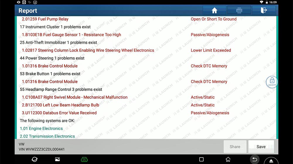
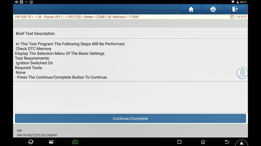
How to perform "DSG Transmission Basic Setting†for VW Passat 2013 with the guided function of Launch X431 PAD V. It is applied to X431 Pro V4.0, X431 Pro3 V4.0, X431 Pad VII etc.
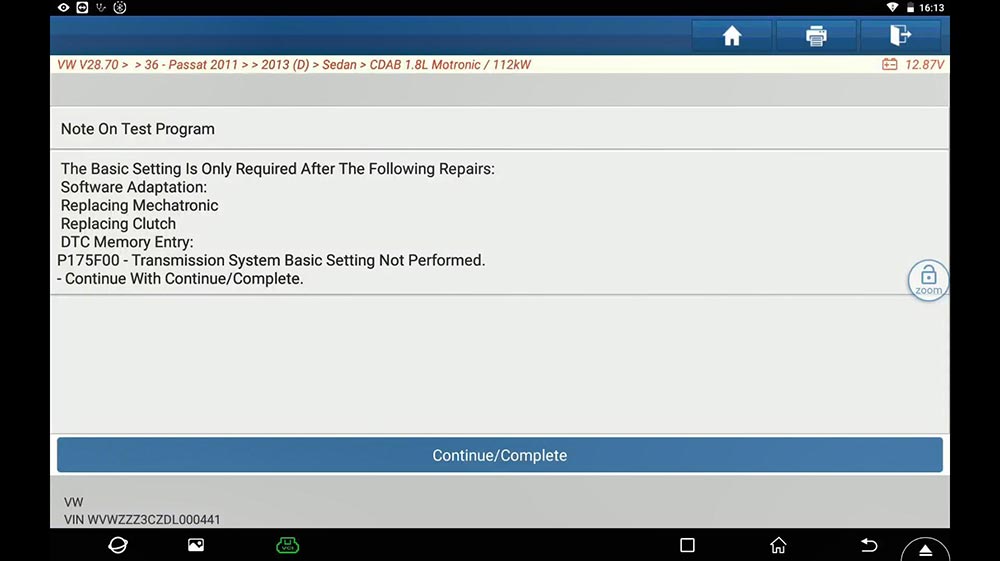
After change DSG Transmission, DSG clutch pack, DSG mechatronic, DTC -P175F00, transmission basic setting not perform. It is required to do DSG Transmission Basic Setting.
Here is the report.
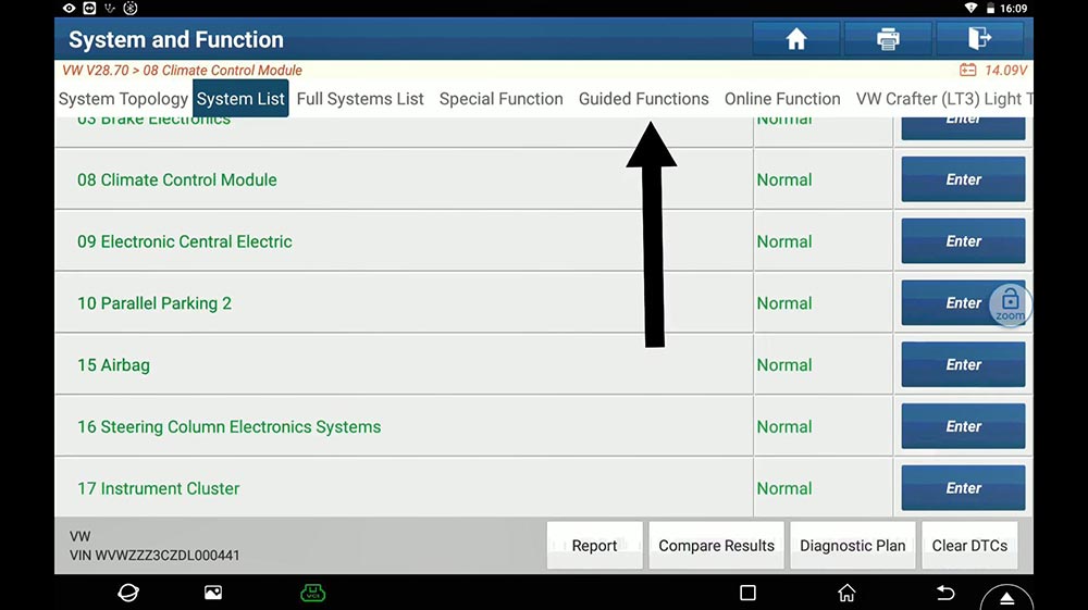
First "System List†and then "Guided Functionâ€.
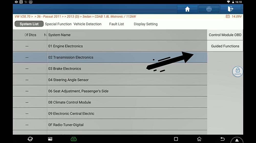
Choose the basic vehicle information: Passat 2013 Sedan.

Choose †Transmission Electronics†and then "Guided functionsâ€.
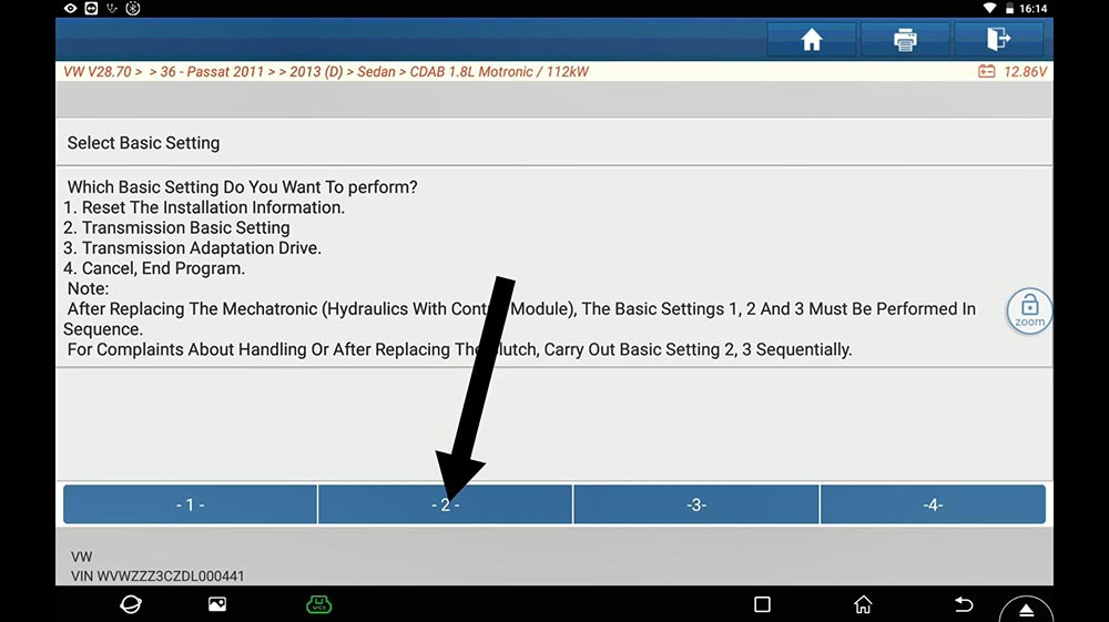
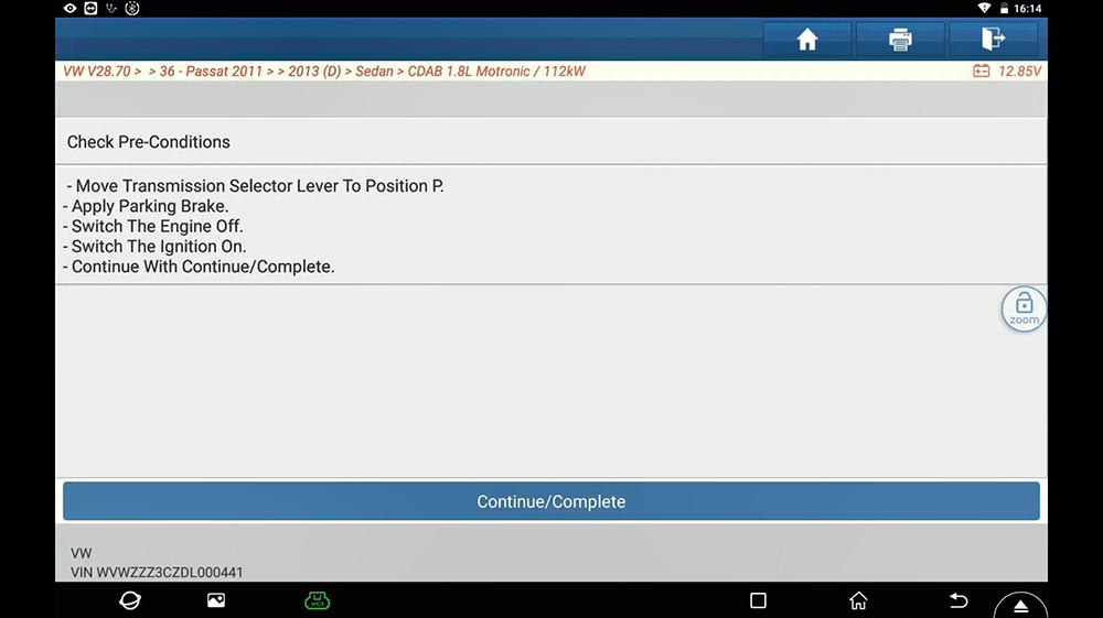
Choose "J743 – Mechatronic, basic settingâ€.
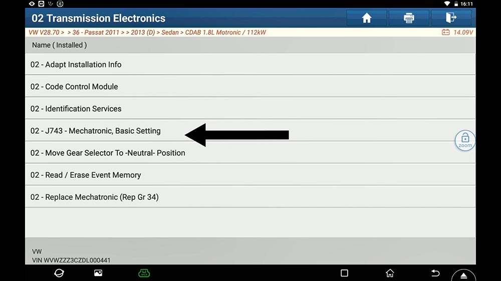
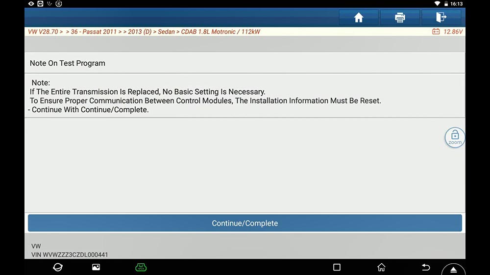
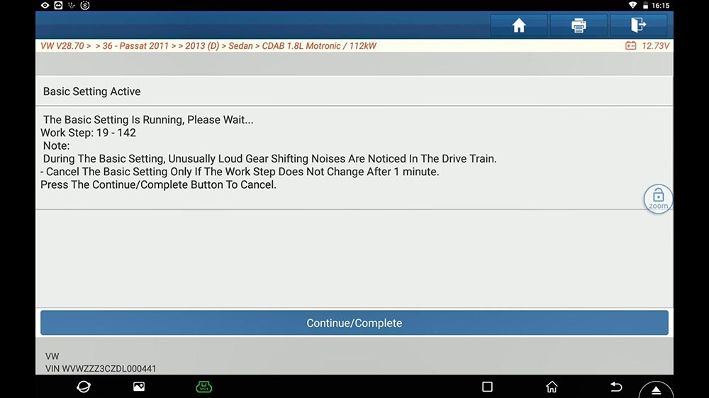
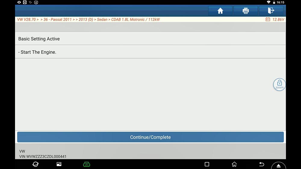
Next is to follow the on-screen guide to perform:


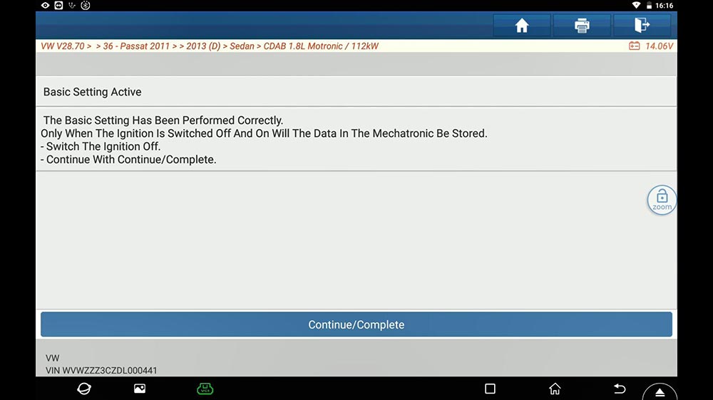


Finally, test drive and done.

Thumb up Launch diagnostic tool X431 PAD V, X431 Pro V4.0, X431 Pro3 V4.0, X431 Pad VII.
Posted by: obd2tool at
05:33 AM
| No Comments
| Add Comment
Post contains 132 words, total size 8 kb.
October 07, 2021
The registration, updates, language changing, data log uploading of Autel professional scanners, especially Autel MK808 is quite important for new starters/users.
For this article is going to share with you guys the updates on firmware part, that is, the vehicle connector interface for Autel devices.
You also have to know: the process is also the same among the kind of Autel products.
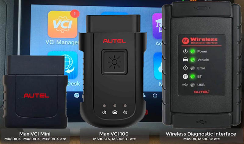
Main Autel VCI types:
MaxiVCI Mini: for MK808TS, MX808TS, MP808TS etc.
MaxiVCI V100: for MS906TS, MS906BT etc.
Wireless Diagnostic Interface: for MK908, MK908P etc.
1.Update via display tablet
Caution:
Ensure device is well charged
Connection to VCI is firm
Internet connection is stable
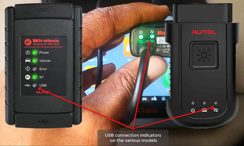
1)Connect the VCI to the tablet via the USB cable.
Once the two green lights on, thing are connected well.
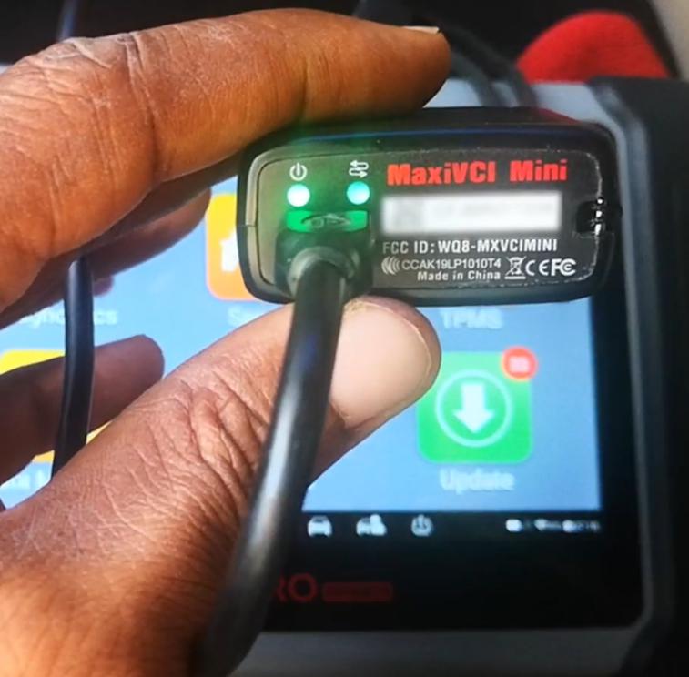
For other VCIs, there will be similar indicators.
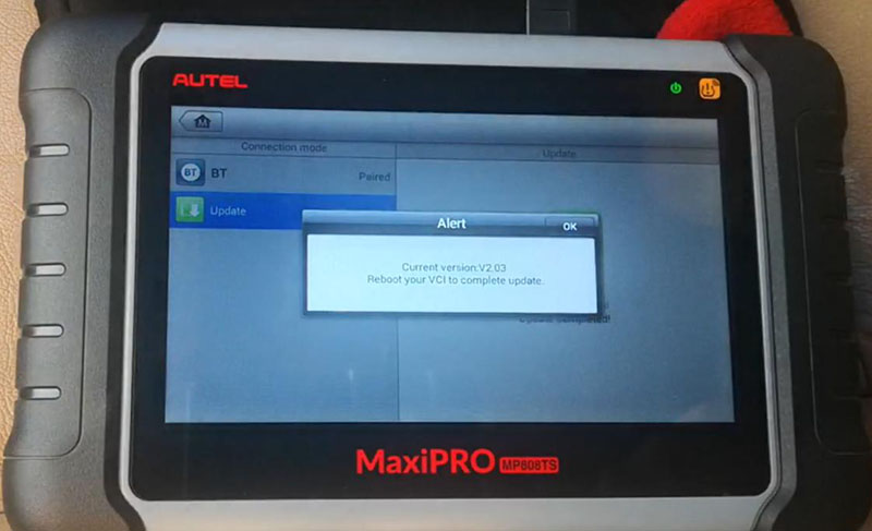
2)On homepage, press
VCI Manager>>Update
Wait for the pairing of the device and the VCI.
Then click on "Update now†to download the latest version.
Reboot your VCI to complete update.
2.Update via PC
1)Download and install "Maxi PC Suite†from www.autel.com.
Support>>Downloads>>Maxi PC Suite
2)Connect the VCI to PC via the USB cable.
3)Launch "Maxi PC Suite†and select your VCI type
4)After the update tool recognize the VCI automatically, choose an available version to update.
Completed! Nice professional tool that you derseve to have.
That’s all. Thank you for sharing your time with us!
Posted by: obd2tool at
05:50 AM
| No Comments
| Add Comment
Post contains 237 words, total size 3 kb.
My friend has a 2012 Chevy Equinox that uses newer GM network platform. No diagnostic coverage using a GM Tech2. The Equinox has been suffering some BCM problems lately with no way to plug in.. Only thing I could get was powertrain codes using a cheap scanner.
Anyway GM MDI 2 Used. I got a good MDI clone from atrustedsource OBD2tool.com. I have used this site since July 2009.
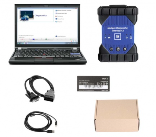
Bought amdi2 wifi version with a hard drive. Came in today. It uses a laptop.
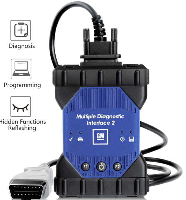
https://www.obd2tool.com/goods-10445-GM-MDI-2-GM-Scan-tool-Plus-Lenovo-X220-Laptop.html
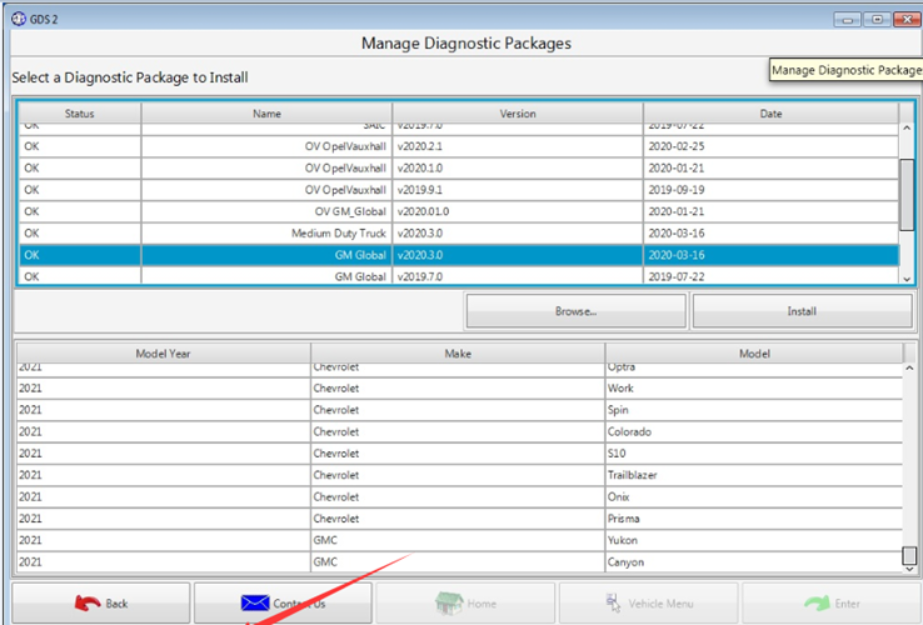
works well, would recommend cloning HDD, as they seem to be easy to
wipe it windows does a check disk. The HDD has many different packages
to install as needed. I have used on the Chevy, will try on a Buick next
time I have one to work on.
This interface can do system diagnostics and ….added bonus….program replacement modules.
There is a MDI 1 version too. I don’t mind if clone mdi 2 is same as mdi 1. I saw people using it without a problem.
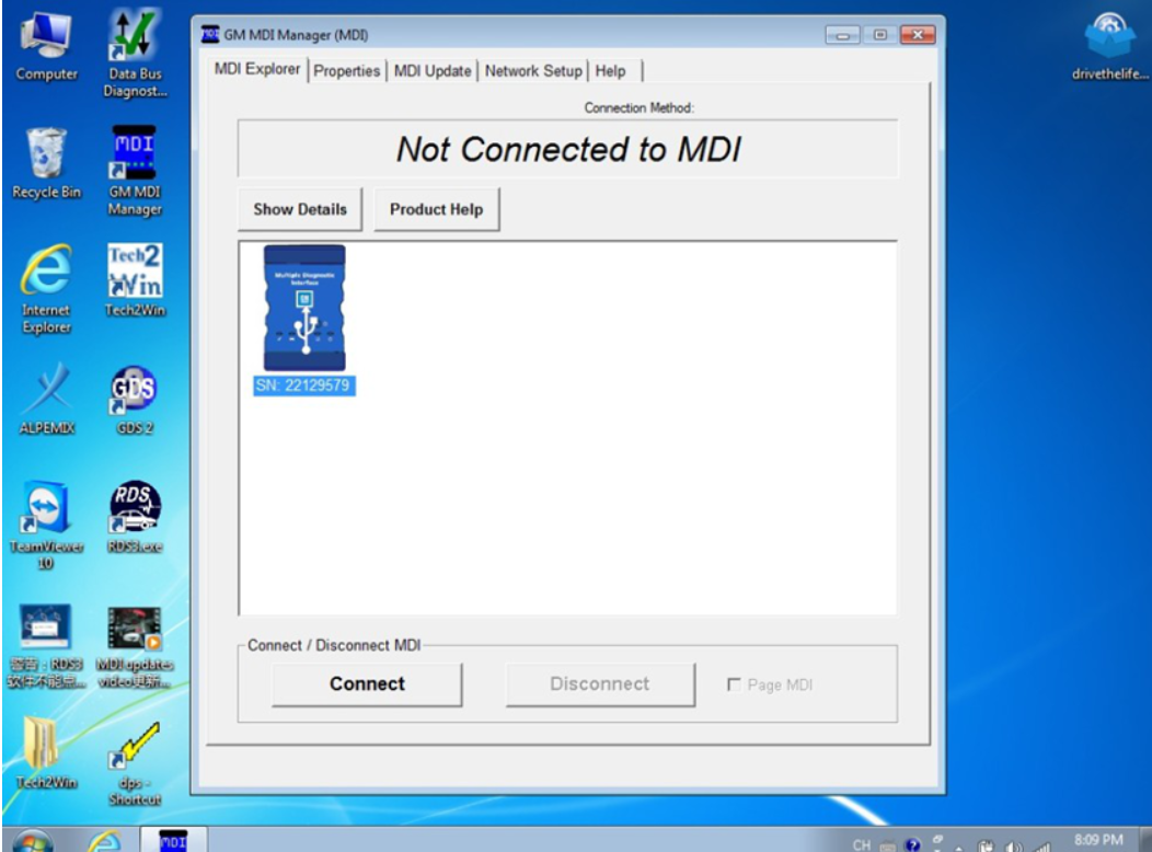
Lenovo X220 Laptop is now setup with the GM MDI 2 manager software. GDS2 identifies it as aMDI2.
So then wireless GM GDS2 diagnostics from home network(using ACDelco 3
day subscription)tolaptop in garage…..then wireless from laptop to the
MDI 2 in the car 30 feet away….it does work.
Lots of BCM codes. Equinoxmain problems were the wipers and washer
would cycleon at key on…..4 way flashers were coming on 30 minutes
after key off. Both go thru the BCM.
Equinox is fixed with a new BCM. Ended up having local GM shop program the new BCM.
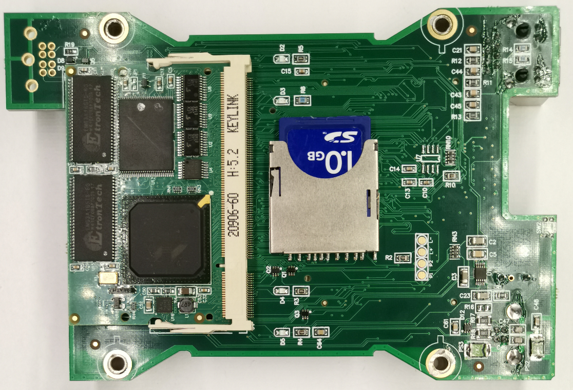
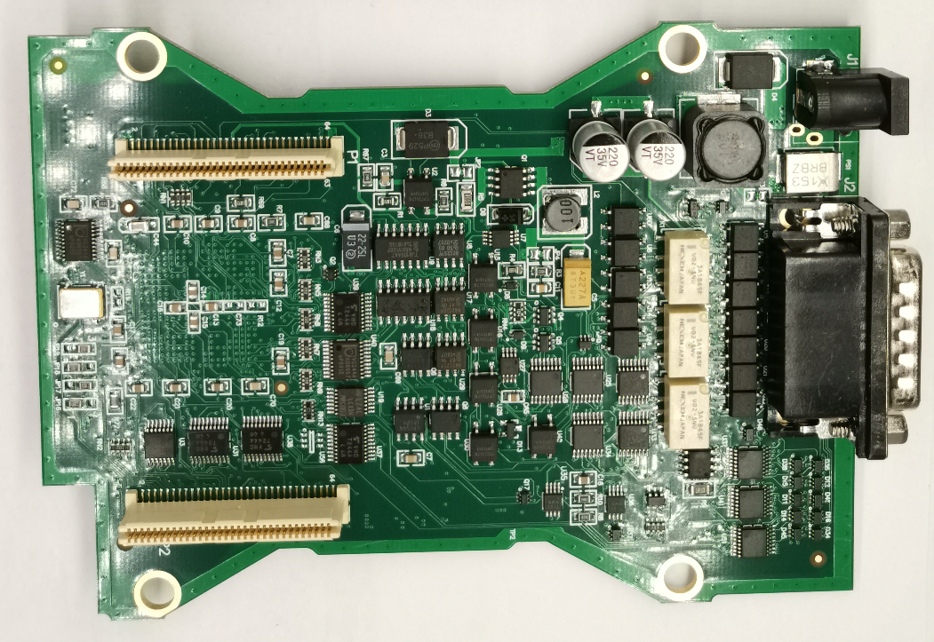
In case someone is interested, these are the PCBs ofGM MDI2 .
Posted by: obd2tool at
05:43 AM
| No Comments
| Add Comment
Post contains 289 words, total size 3 kb.
October 01, 2021
Ford VCM 2 with Ford IDS Software for Ford diagnostic & programming. Quality Ford VCM2 can work with oringinal Ford IDS software from Obd2tool.com, Ford VCM2 Ford diagnostic tool also support firmware update. Here share How to use Ford VCM 2 reprogram Existing Module Step by Step.
Ford diagnostic Tool Ford VCM 2 Clone with Ford IDS Software

Obd2tool.com Ford VCM 2 with IDS Ford diagnostic software reprogram an existing module, follow these steps:
(please connect the cloned Ford VCM2 unit to the car and run Ford IDS)
Step 1:Select the toolbox tab at the top of the screen
Step 2: Select "Module Programmingâ€
Step 3: Select the tick mark or the Enter key
Step 4: Select "Module Reprogrammingâ€
Step 5: From the fly out menu, select the type of module to be reprogrammed
Step 6: Select the tick mark or the Enter key
Step 7: The application will compare the current calibration level to the latest one available for thatvehicle. A message will appear.
Step 7A: If no later calibration is available, a message will appear indicating this. Select the tickmark or the Enter key to return to the Module Programming menu.
Step 7B: If a later calibration is available, a message will appear asking if you want to reprogramthe module with this calibration. If you do not want to reprogram the module, select "Noâ€. You willbe returned to the Module Programming menu.
Step 8: If you want to reprogram the module, select "Yes†in response to the question "Do you wantto program the vehicle with this calibration?â€
Step 9: Make sure that an Internet connection has been established and then selectâ€Confirmâ€
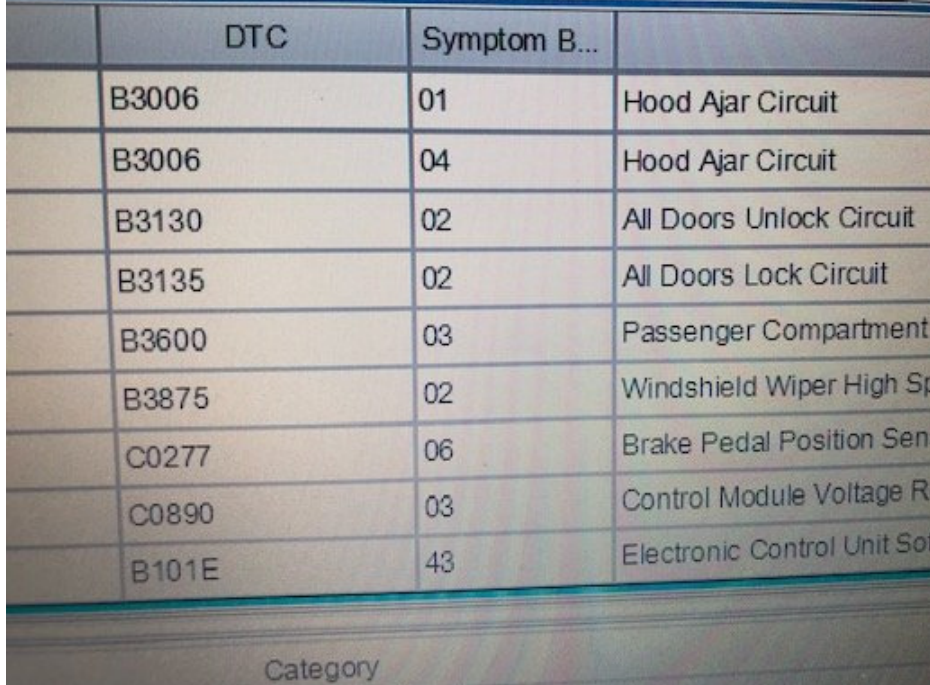
Step 10: You will be presented with a screen that recommends that you carry out Self Test. If youchoose to complete this test, you will receive a list of Diagnostic Trouble Codes (DTC’s) that havebeen set on the vehicle. When finished viewing this list, select "Exitâ€.
Step 11: Follow the on-screen instructions to prepare the vehicle and turn the ignition key off and on.
Select the tick mark or the Enter key after each one.
Step 12: If necessary, apply the reprogramming label to the PCM
If an emissions recall has been performed or a required emissions-related TSB has been completed,an Authorized Modification label must be placed on the PCM. These labels can be purchased at theparts counter of a Ford or Lincoln/Mercury dealership.
Step 13: Select the tick mark or the Enter key to return to the Module Programming menu.
Ford VCM 2 important note for PCM reprogramming:
Ford VCM2 IDS Error Code:11.0×0 851082 when PCM reprogramming
It’s aimed to help how to reprogram/reflash Ford PCM via IDS software esp. for those with Error Code:11.0×0 851082 will be shared here by other users.
Error message:
"The operation cannot begin because the PCM failed to complete a service procedure. Perform PMI on the PCM to resolve the issue.â€
Possible scanners working with:
VXDIAG VCX NANO Ford
Ford VCM2 clone
Customer solutions:
Customer A:
Turnoff your firewall
Customer B:
Uninstall fmp and reinstall it. I have had this happen before.
I have had some new pcm be un programmable.
And just for reference. Fmp doesn’t like Google. Use 32 bit processor as well.
I had to slow my computer down from 64-32 because fmp would not work correctly with 64.
Good luck.
Customer C:
If you are checking PCM for up-dates, Ford will advise on 6.0L powertrain if there is a reflash avail for TCM, FICM or PCM, if it states there is no update then all three modules are at latest level, no action required, I am aware it states to remove FICM relay prior to reflash FICM, this is a carryover note from when we used PDS or WDS to reflash the FICM, if you are using IDS with VMM interface its not required to remove the FICM relay, I have reflashed over 1000 of them this way over the last 7 years, as always make sure the battery stays in the sweet spot @ 13.5 volts, make sure your laptop has sufficient power, I always plug in, make sure cables to veh and laptop are safe from accidental disconnect, Good luck!
Customer D:
If you try to VCM2 genuine or clone to make reprogaming well you need IDS V98.01 or higher.
It would be good to check if during initiation programming interface output 18,5V on pin 13 in OBD connector.
More question about Ford VCM 2Ford Diagnostic Tool with Ford ids software just keep your order number to contact us freely.
https://fordtroublerepair.blogspot.com/2021/08/how-to-use-ford-vcm-2-reprogram.html
Posted by: obd2tool at
09:37 AM
| No Comments
| Add Comment
Post contains 766 words, total size 6 kb.
GM’s new Vehicle Intelligence Platform, or VIP, currently used on 2020-2022 Corvette, CT4, CT5 and 2021-2022 Tahoe, Suburban, Yukon, Escalade and Envision models, offers increased capacity and the ability to better manage technology complexity.
With a fivefold increase in system capacity and responsiveness over the current Global A system, the next-generation VIP electrical architecture offers the capability of managing over 100 computer modules. It’s able to support active safety systems, Over-the-Air (OTA) vehicle software updates, 5G networks, enhanced cybersecurity protections and EV technologies.

The VIP electrical architecture includes two-wire CAN buses and two-wire Ethernet buses to ensure high speed data transfer and multiple single-wire LIN buses to exchange information between master control modules and other smart devices. Low speed General Motors Local Area Network (GMLAN) networks are no longer used in VIP vehicles.
CAN Protocol
The VIP architecture communication protocol is based on the widely used CAN (Controller Area Network) protocol. CAN buses are used where data needs to be exchanged at a high rate, primarily by a control device using the information to adjust a vehicle system, such as powertrain or body controls. Each CAN data network consists of two twisted wires, called CAN (+) and CAN (-), with a 120 ohm (Ω) termination resistor at each end of the bus between the CAN (+) and CAN (-) circuits.
Ethernet data communication technology uses a single twisted copper pair of wires at speeds of 100 Mbit/s and 1000 Mbit/s. The Ethernet system uses point-to-point communication that is connected via an Ethernet switch [Module <–> Switch <–> Module]. The Ethernet bus does not use terminating resistors.
The K56 Serial Data Gateway Module and the A11 Radio have an Ethernet switch that connects to other Ethernet modules. These modules communicate with other devices and systems in the vehicle via CAN and LIN buses. DTCs will be read on CAN to diagnose Ethernet, LIN, and system faults.
Any Ethernet harness failures should be repaired only using the appropriate kit to perform de-pin/re-pin overlays. In cases where the wiring harness repair kits are not available, the entire harness should be replaced. No crimps or splicing should be performed on the Ethernet wiring harness.
Serial Data Gateway
To signal any loss of communication and set DTCs, the K56 Serial Data Gateway Module must know and learn the control modules on the vehicle and their associated buses. If the Serial Data Gateway Module is replaced or another module is added to the bus, such as a dealer-installed accessary, a learn process must be done using the Serial Data Gateway Module learn procedure in SPS.
The learn process will not cause any previously learned contents to be forgotten or overwritten. If the learn process is not completed on a new Serial Data Gateway Module, DTC U1977 (ECU Identification Self Learn Not Completed) will be set until the learn procedure is performed. If the learn process is invalid due to internal malfunction or a Serial Data Gateway Module swap, DTC U3000 42 (Control Module – General Memory Failure) or DTC U3002 56 (Vehicle Identification Number – Invalid/Incompatible Configuration) will be set. The Serial Data Gateway Module will then lose communication with all control modules and set DTCs against control modules not on the vehicle.
The Serial Data Gateway Module also functions as a gateway to isolate the secure networks on the vehicle from unsecured networks. Isolating primary networks helps ensure advanced driver assistance systems and active safety features, such as enhanced collision avoidance, can all operate in conjunction with each other. If harmful software enters the vehicle through the infotainment system, OnStar, or the DLC, other vehicle systems may be affected.
Power Moding
In the VIP architecture, the K9 Body Control Module (BCM) is the Power Mode Master (PMM) and the K56 Serial Data Gateway Module is the back-up PMM. There are five power modes: Off, Accessory, Run/Service Mode (Engine Off), Propulsion (Engine On), and Start. As the PMM, the BCM uses a number of vehicle states and inputs to determine which power mode is required. It reports this information to other modules via serial data.
MDI 2 Required
The EL-52100GM MDI 2 is required for control module programming, configuration and setup on vehicles equipped with the VIP architecture. The MDI 1 does not have the capability to complete programming and setup procedures. Using an MDI 1 on these vehicles could result in erroneous data or failed programming events that could lead to unnecessary module replacement.
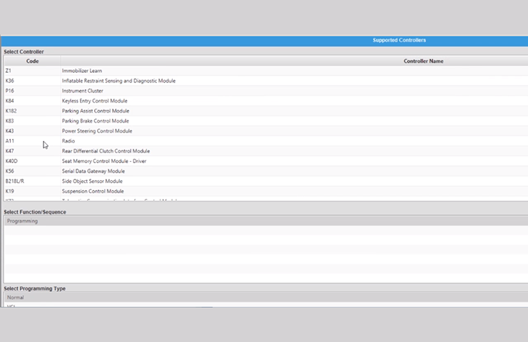
When a scan tool is installed, it will attempt to communicate with every control module that may be available on the vehicle, depending on optional equipment. If an option is not installed on the vehicle, the tool will display No Communication for that control module. In order to avoid misdiagnosis of a No Communication message, refer to the Data Link References that lists the control modules and the buses with which the modules communicate in the appropriate Service Information and the vehicle build RPO codes to determine optional control modules.
Programming a Module
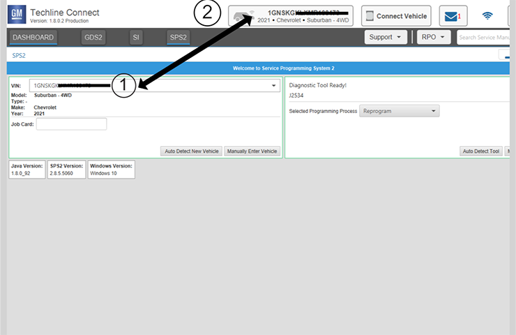
When SPS (Service Programming System) programming a module (Fig. 2), follow all SPS on-screen instructions.
These tips also should will help in successful programming:
Confirm the VIN – Techline Connect (TLC) does not automatically execute the Vehicle Identification Number (VIN) Read with the power mode Off. Technicians must confirm that the VIN is correctly identified prior to programming by verifying the VIN reflected in Techline Connect matches the VIN plate on the vehicle. (Fig. 3) Be sure not to select a VIN that is already in the Techline Connect application memory from a previous vehicle.
To use the VIN Read when using Techline Connect, the vehicle’s power mode (ignition) must be On before reading the VIN from the vehicle’s Engine Control Module (ECM), which is the vehicle’s VIN master module. Programming or reprogramming modules with the incorrect VIN and using software and calibration files from incorrect VINs can cause future serviceability issues as well as potential vehicle performance issues that may require the vehicle to be reprogrammed again.
Battery Voltage – Stable battery voltage is critical during programming. Any fluctuation, spiking, over voltage or loss of voltage will interrupt programming. Install a GM Authorized Programming Support Tool to maintain system voltage. Do not use a battery charger.
Power Mode Off – The power mode (ignition) must be Off to begin module programming. Any load on the vehicle’s battery, such as interior lights, exterior lights and Daytime Running Lamps, and HVAC operation, may affect the download process and may cause errors to occur.
Do Not Change the Power Mode – Do not change the power mode of the vehicle (position of the ignition switch) during the programming procedure unless instructed to do so. Programming will direct the appropriate control module(s) to change power mode as needed during the procedure, independent of the vehicle’s power mode.
Keep Vehicle Fully Asleep – Ensure that the vehicle will not become awake during the programming event by keeping all doors closed (vehicle fully asleep). For access to the vehicle, trip the driver’s door latch to the closed position so that the door can remain open. If a closed door is opened during programming, buses will wake up and cause error codes to set
Clear All DTCs – After programming, clear all DTCs and allow the vehicle to go into sleep mode. DTCs U1962 (Unable to Authenticate Serial Data Message) and U1983 (Serial Data Gateway Module Security Hardware Internal Malfunction) may set and the Check Engine MIL may illuminate if the DTCs are not cleared and the vehicle does not go to sleep after programming or Serial Data Authentication Configuration (SDAC).
If SDAC fails, DTC U1962 will set as a current DTC. It will not clear until another programming event occurs that runs SDAC, or the standalone SDAC procedure is performed using SPS. If DTC U1962 is stored only as a history DTC and not retrieved as a current DTC, do not perform the SDAC procedure.
Wait 5 Minutes – After programming, let the vehicle sit for five minutes with the ignition Off, Retained Accessory Power Off and the key fob removed from the vehicle after completing programming. After five minutes, the system can be operated to verify repairs.
https://gmscantool.blogspot.com/2021/08/programming-with-vehicle-intelligence.html
Posted by: obd2tool at
09:32 AM
| No Comments
| Add Comment
Post contains 1363 words, total size 11 kb.
32 queries taking 0.0859 seconds, 150 records returned.
Powered by Minx 1.1.6c-pink.

