


August 30, 2020
How to use Launch X431 proS mini to activate the PCM Aux input on 2018 Porsche 991.2 ?
Car model and year: 2018 Porsche 991.2
Purpose: activate the PCM Aux input
Porsche diagnostic scanner:
with Launch X431 V+ Pros Mini
was able to activate the Aux setting without any problems.
Look at the screenshots for X431 ProS Mini activating the Aux input on PCM 4.0
First go to the system PCM/CDR. Search for "Auxâ€. Select Aux_IN
Change Aux_IN to "Onâ€
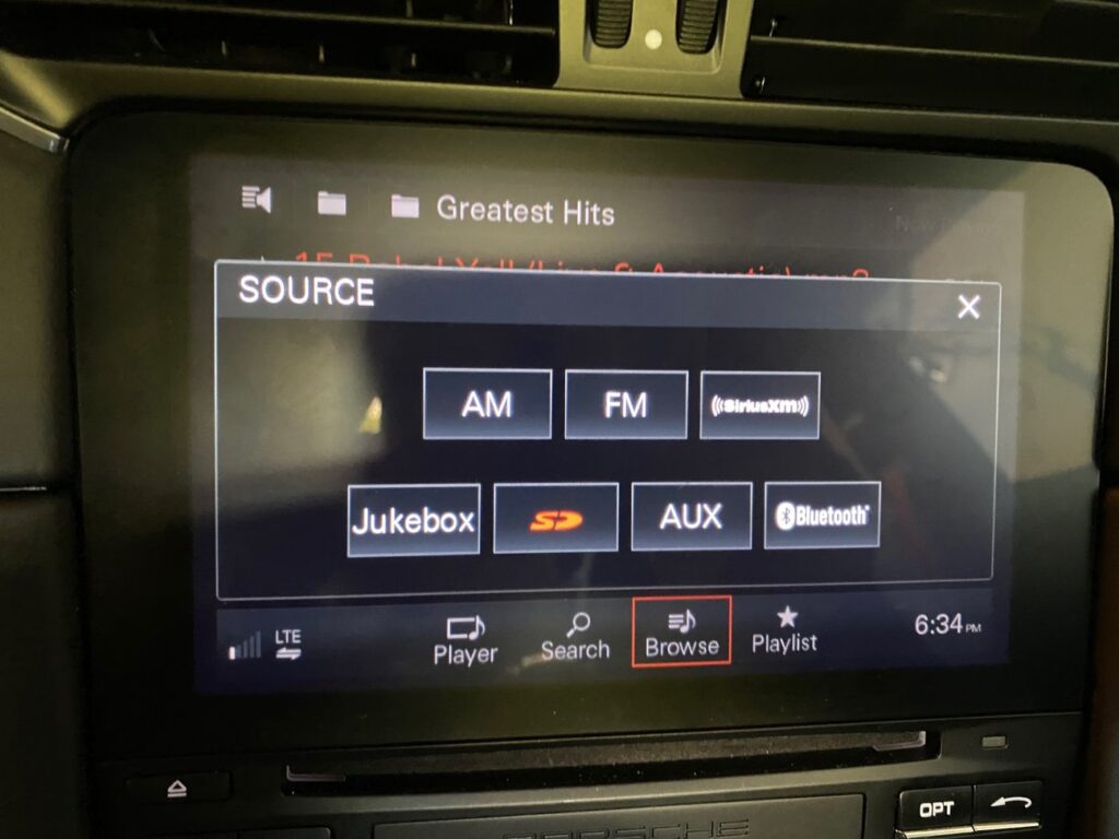
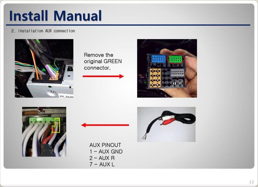
I also added a Aux cable to the green connector on the back of my PCM. It connects to Pins 1 (Ground), 2 (Right) and 7 (Left).
Enjoy!
Posted by: obd2tool at
03:08 AM
| No Comments
| Add Comment
Post contains 118 words, total size 2 kb.
I have Chevrolet Corvette, looking for a scan tool that doesn’t break the bank that will help to determine why I get no crank and some other seemingly related issues.
The year of engine / PCM:
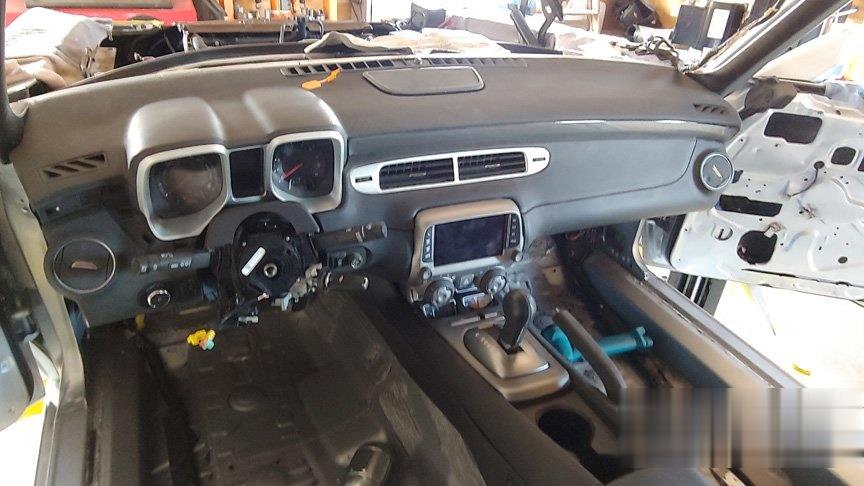
The entire project is a transplant of a running and driving 2014 Camaro SS A8 into a 70 Chevelle Malibu. The only things I gave up were the ABS, seat belts, airbags, sunroof and HUD. All the original parts and harnesses, except the door latches and lights.
What I tried to do:
I got my cheap vxdiag gm scanner to give me some codes and I now may know what is happening. The shop foreman at a local dealership told me that the absence of the fuel pump from the wiring harness (and therefore the CAN bus) wouldn’t cause a no crank condition. However, the codes only talk about the CAN bus failing and the fuel pump response and so now I suspect that the absence of the pump is the cause of no crank cause, or at least it’s contributing to the issue.
The reason the fuel pump and tank are not installed is that I was waiting until I was ready to actually start the engine. The wiring harness for the fuel pump/tank was cut and an 8′ section was crimped, soldered and heat shrunk into the area under the back seat; that was where the harness went through the floor which was close to the Camaro tank.
Although I verified the splices, twice, my concern was that I didn’t want to test the new wiring with gas in the tank and I thought that sooner or later I would plug the pump in without the tank; I guess the time is now. We’ll see if the codes change – maybe tomorrow.
BTW, if you run your pump without gas in the tank or hanging from the rear end, be sure to only let it run for a few seconds. It actually uses the fuel as a lubricant.
I would just like the ECM to talk to the OBD2 scanner and fire up the starter motor. The rest of it will come later. I plugged in an OBD2 scanner and all I could get was "ECM (or is it ECU) not respondingâ€. I assume that means the BCM is responding. But I don’t know for sure since the BCM is compartmentalized; some of the BCM stuff does work, like the exterior lights, radio and NAV. Since I know that some of the BCM stuff is not working I suspect that I may have a missing ground under the dash cover. Don’t look forward to taking that all apart. Couple of pics of the current state of the dash below.
Have checked every fuse Might be time to unplug all the cables and check for bent pins.

I’ve isolated the problem to the GMlan/CAN bus and found an open in the circuit; I can see both 120 ohm resistors but only from two different points in the circuit. From contacts 6 & 14 on the odb2 connector, you should read 2 120 ohm resistors in parallel or 60 ohm; I only see the one resistor at the end of the line, the one at Fuel Pump Control Module when connected to the ODB2 pins.
From pins 14 and 26 on the ECBM, I can see the one built into the ECM, but only from the Electronic Brake Control Module (EBCM). On ECBM pins 15 and 27 I see 20 ohms which is very confusing.
Continuity thru the FPCM and EBCM is solid. This is a requirement for testing; when the circuit is dry (battery disconnected) you need to be able to test the circuit.
The attached drawing with its notes is originally one I found on LS1tech or on Camaro5, and I’m not absolutely sure it’s for a late model gen5, but it is an update from the early gen5 drawing. My notes are from my testing.
I could not find two of the modules the drawing shows – Headlamp Leveling Control Module (believe this vehicle didn’t have it – see TR6/TR7) and the Automatic Transmission Assembly.

Thanks to @ Dano523 for his advice:
Tech IIclone, and if you have a laptop, then this will fit the bill.
VXDIAG VCX Nano Multiple GDS2 and TIS2 WEB Diagnostic/Programming System
Hence is a MDI clone that comes with Tech2win, and works just like the same tool that the dealers use. Better yet, since it is a MDI clone, will work not only on older GM cars, but the latest GM cars as well. Hence C6 and older vets uses Tech2win software. while the c7 and up cars us GDS2 instead (which is comes with both /will run both as well.
I have both vxdiag vcx nano gm wifi version and vxdiag vcx nano gm usb version, and the glitch with the Wifi version, is you have to have it connect to the car and car on for it to power up.
So every time you turn the car off, then back on, you have to go back and restart Tech2win to reconnect the nano to Tech II software.
Also, I like to have the Nano connected to Tech2win before connecting the the car, So when I use the Wifi unit, just use it USB cable style to solve the connect/reconnect problems.
To add, when using the nano with Tis2000 and even TDS, need the laptop to stay wifi connected to the internet, and not an easy way to pull off by connecting to wifi Nano and the Wifi internet at the same time on most machines.
Posted by: obd2tool at
02:36 AM
| No Comments
| Add Comment
Post contains 951 words, total size 7 kb.
August 11, 2020
This article show a guide on how to use Nissan Consult 3 Plus to diagnose/read trouble codes for Infiniti FX35/FX45 2003.
Diagnosis Procedures:
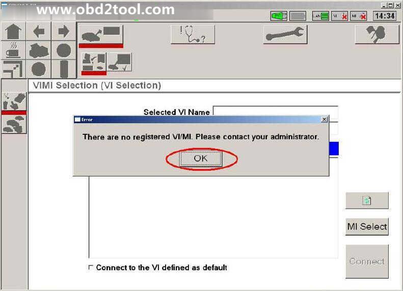
1.Open "CONSULTIII†on the desktop.

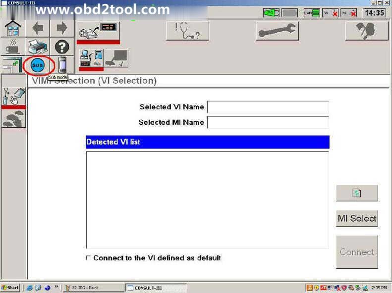
2.A window pops up reading "There is no registered VI/MI. Please contact your administrator.†Click "OKâ€.
3.Click "Sub modeâ€
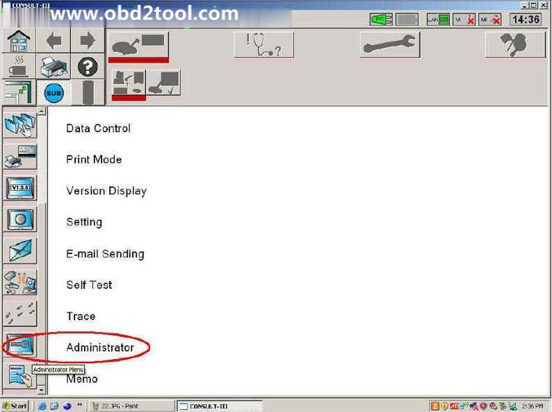
4.Click "Administrator Menu†on the left menu list.
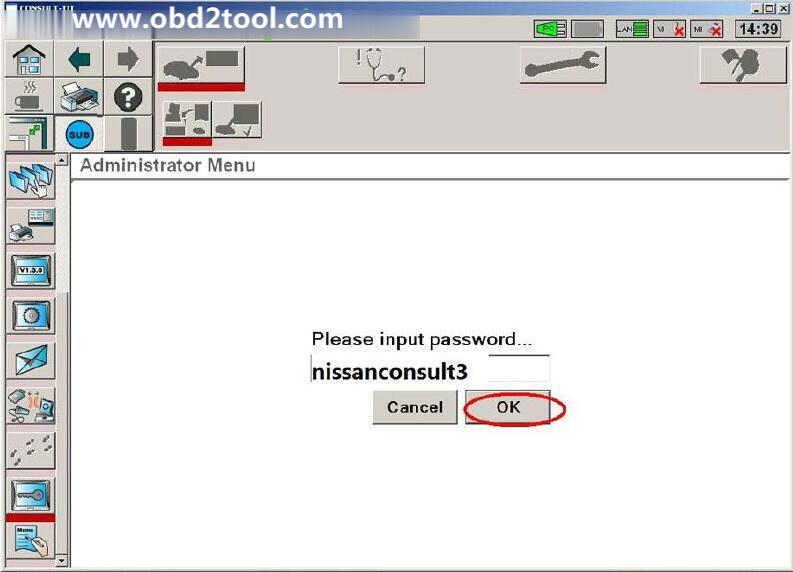
5.Please input password… "nissanconsult3â€, then click "OKâ€.
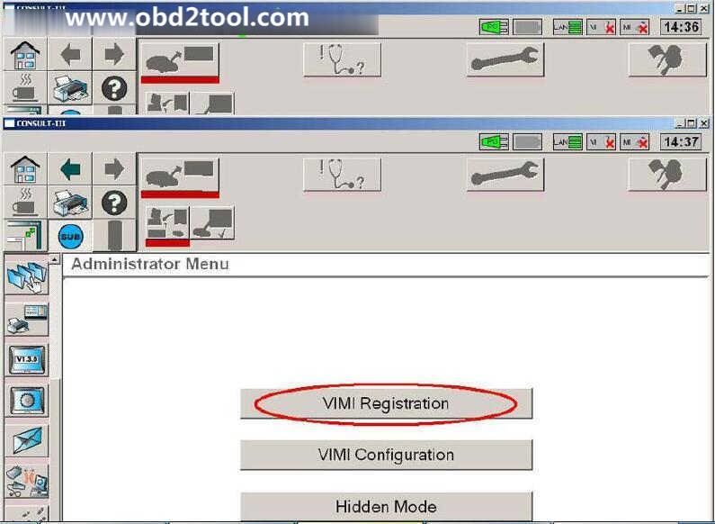
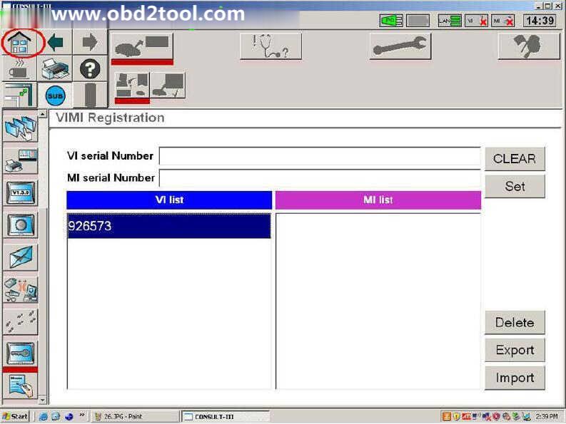
6.Click "VIMI Registrationâ€
7.Input "VI serial Number†and then click "Setâ€.

8.You can see the VI serial number under "VI listâ€
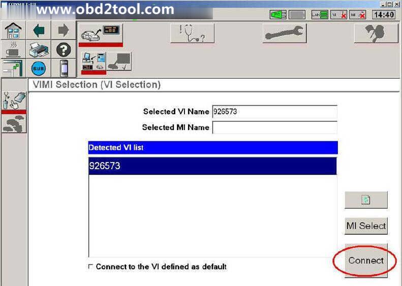
9.Detected VI list, click "Connectâ€.
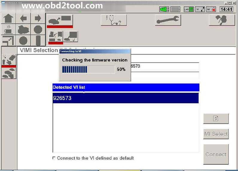
10.Checking the firmware version.
11.Select Vehicle Name and Model Year, then click "Selectâ€.

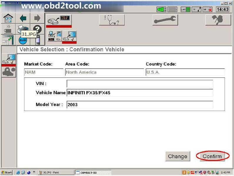
12.Click "Confirm†to confirm the information: Market Code, Area Code, Country Code, Vehicle Name and Model Year.
13.Select System.
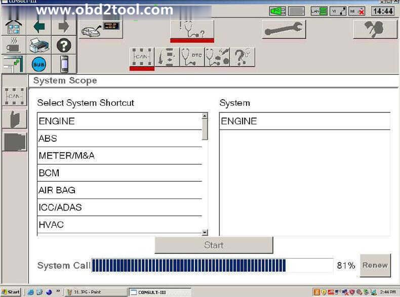
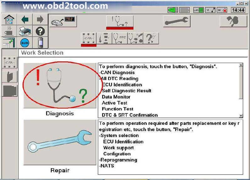
14.Select Diagnosis
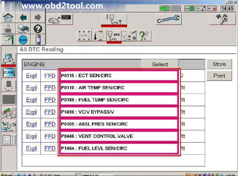
15.Read out trouble codes.
Now it show the diagnostic trouble code as below,and you need to check the problem according to the DTCs,after then clear them.
Posted by: obd2tool at
08:05 AM
| No Comments
| Add Comment
Post contains 159 words, total size 8 kb.
What Nissan Consult 3 Plus?
Nissan Consult 3 Plus is a diagnostic software special for Nissan,support all the models of the Nissan and Infiniti from 1996 up till now, with all Consult II & III functions.It can support all Nissan car,Infiniti carand Nissan GTR.
Nissan Consult 3 Plus Functions List:
Supports ECM reprogramming on most 1999 model year and later and some TCM and ABS/VDC reprogramming.
Supports blank ECM and TCM programming.
Supports ECM reprogramming on most 1999 model year and later and some TCM and ABS/VDC reprogramming.
Supports blank ECM and TCM programming. September 2013 Nissan and Infiniti began the phase-in of "blank†service part ECMs and TCMs. Depending on the model and model year, replacement modules come WITHOUT software. When the replacement module is installed in an applicable vehicle for any reason, it will need to be programmed.
Optional Security Card-Type A Kit must be approved security professional to purchase
Nissan Consult 3 Plus Specifics:
PC Based: PC Require
Model Year Coverage: The Consult-III Plus is required for all 2013 and newer Nissan and Infiniti vehicles. In addition, the Consult-III Plus is required for all: 2011 and newer Nissan LEAF, Quest, and Murano CrossCabriolet vehicles; 2012 and newer Nissan GT-R and NV vehicles; and 2012 and newer Infiniti M and M Hybrid vehicles. The Consult-III Plus software is continuously being updated to accommodate new vehicles as well as older model years dating back as far as 1996.
PC Recommended: Nissan Specific, Panasonic Toughbook
Software License:https://www.nissan-techinfo.com/
Nissan Consult 3 Plus Support Car Models:
Diagnostics:for all Nissan,Infiniti,GTR
Immo and Smart key:for all Nissan,Infiniti,GTR
Nissan GTR: for Nissan GTR Diagbostics and Immobi
Electromobiles car:for Nissan Electromobiles car Diagbostics and Immo
Nissan and Infiniti from 1996 up till now
Note:Consult III Plus – 1996MY up
Nissan Consult 3 Plus Support Languages:
English, Portuguese (Newly Add), French, German, Spanish, Italian, Japanese, Russian, Finnish, Greek, Chinese(Simplified), Chinese(Traditional)
Nissan Consult 3 Plus Installation OS Requirement:
Operating System Environment
* Windows: Windows? 2000, Windows XP, Windows Vista, Windows 7, 8 or 8.1
* Mac: Macintosh 8.x, 9.x, OS X
* Disk Storage: 10 MB available hard-drive space
* Display Resolution: 800 x 600 pixels (1024 x 768 recommended)
Nissan Consult 3 Plus Installation Guide:
The installation methods of different Consult 3 may be similar,if there here is no version that you have or you have higher version,please try to install it referring to these method by yourself.
How to Install Nissan Consult 3 III Plus Diagnostic Software
Nissan Consult 3 Plus Free Download:
Nissan consult 3+ plus V83.11.00:
https://mega.nz/#!D9ZRnaSL!Y6rksoTqF1rbpx2-tIvliYFN5RcQSb6s-WwKqBGByZI
Nissan Consult 3+ Plus V81.11.00
https://mega.nz/#!ukhgRSYJ!DXM22QAbQDo-b4Di9e6tyxy2SE4fKVogLmKCv6QzZUA
Nissan consult3 plus V75.20 free download:
https://mega.nz/#!WYYmiQ6J!QDCblZBomUBfEkTUEHd9ZCHWzV0cUKM-_3fT0nW7scg
Nissan Consult 3 Plus V72.13 free download
https://mega.nz/#!EVBC1I6a!mwvSkwf4SKqBN0oYDAhpvWJNFPHdWSKHKGaKgXknkSw
Nissan Consult 3 Plus V71.11.00 & 71.20.00 from 05.2017
https://yadi.sk/d/GsZoo_VD3KxqER
Posted by: obd2tool at
07:25 AM
| No Comments
| Add Comment
Post contains 463 words, total size 5 kb.
July 07, 2020
Question:
What is the latest PIWIS software of vxdiag tester iii? How can i update software to latest version?
Obd2tool.com solution:
The latest VXDIAG PIWIS III software goes to 38.900.000 (Till April 2020)
What’s new in PIWIS III 38.900?
38.900 with for the experts the developer/engineering mode activated to code without passing through the Porsche server.
Older software version 38.400 with unlimited activation, with a full engineering menu. You can install a fresh version, 38.900 (the engineering menu has been cut down). Equipment tested, ready to go.

Language: English, US English, German, French, Italian, Spanish, Japanese, Chinese, Russian, Portuguese
Operating system: Lenovo T440P Laptop Windows 7
How to Update VXDIAG Porsche Tester III?
Software comes in HDD format.
Update method: by sending back the 240G SSD (users need to bear the shipping fee ) or purchasing a new SSD.
Posted by: obd2tool at
11:38 AM
| No Comments
| Add Comment
Post contains 148 words, total size 2 kb.
The coding procedure can be applied to All Porsche Models.
Diagnostic system required: Porsche Piwis II, PIWIS Tester III
PSE retrofit coding is done as follows:
The sports exhaust system button can only be coded on the right-hand side of the switch console.
Code keypad assignment.
REPLACING SWITCH CONSOLE (ALL MODELS) > ENABLING SPORT/SPORT PLUS/SPORT CHRONO PLUS FUNCTION
Information
On vehicles with the equipment variant SPORT/SPORT Plus/Sport Chrono
Plus, a function enable process must be carried out after replacing the
switch console.
1. Determine function enabling code in PIWIS.
2. Connect the Porsche PIWIS Tester to the vehicle and start the System Tester. Switch on ignition.
3. Select the vehicle type and start the PIDT.
4. Select Air conditioning control unit using the cursor keys and press [F12].
5. Select Drive links/checks .
6. Select Function enable using the cursor keys and press [F12].
7. Enter the function enabling code and save it by pressing [F8].?
REPLACING SWITCH CONSOLE (ALL MODELS) > ENABLING SPORT/SPORT PLUS/SPORT CHRONO PLUS FUNCTION > CODING KEYPAD
ASSIGNMENT
1.Connect the Porsche PIWIS 3 to the vehicle and start the System Tester. Switch on ignition.
2. Select the vehicle type and start the PIDT.
3. Select Air conditioning control unit using the cursor keys and press [F12].
4. Select Codings/adaptations .
5. Select Customer-specific settings using the cursor keys and press [F12].
6. Select Keypad assignment and press [F12].
7. Check the button assignment using the switch console.?
7.1. Select function of the switches from the shortcut menu if necessary.?
8. Press [F8] to save the button assignment.
9. The message Data has been written appears on the Tester screen. Press [F12] to exit.
10. Read out the fault memory and erase it if necessary.
11. Check the function of the switch console during a test drive.?
Maintenance of vehicle data
Select Additional menu by pressing F7 .?
Select the Maintenance of vehicle data function. Press F12 until M numbers? appears in the Value group column.?
Select 176 – Sports exhaust system in the Coding value column. When you? touch the Installed cell, a tick appears.?
Save the values by pressing F8 . Wait until the message Modified values have? been buffered appears.?
Press F12 until F8 can be activated.?
Press F8 to write values. Wait until the message Generation of vehicle data is? complete appears.?
Press F12 to switch to Log management. Open the log by pressing F10 and?
check that vehicle equipment 176 Sports exhaust system is displayed.?
Adapt coding
Press F11 to return to the list of control units.?
Select all control units.?
Switch to the Codings/adaptations menu.?
Select Automatic coding. Press F12 to continue. Wait until the message
Coding has been completed successfully appears. Press F12 to continue.?
Once coding is complete, read out the fault memories of all systems, work through any existing faults and erase the fault memories.
Posted by: obd2tool at
11:12 AM
| No Comments
| Add Comment
Post contains 482 words, total size 4 kb.
June 17, 2020
There is something wrong with Renault CAN Clip V195. The device indicator lights only show red, and the alliance sensor cannot be detected, besides that, the OBD cable has a little damage. How to solve?
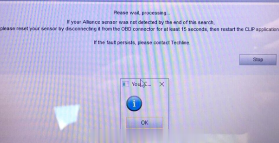
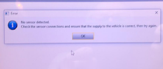
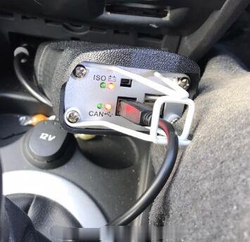
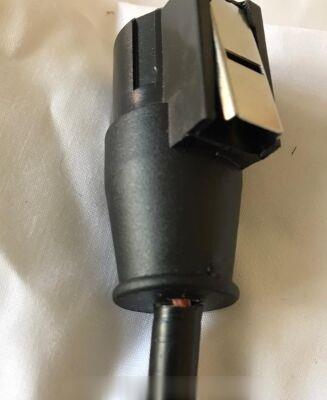
Suggestion:
The OBD cable doesn’t affect the use of V195 CAN CLIP. Please try to install device driver. If it works normal, all the four lights will be on.
Free download Renault Can Clip V195 (03.2020) Torrent:
https://mega.nz/folder/4B4GXYRa#z19USPInTgniFvwe_EKSXw
No password! No risk!
Size: 4.29GB
Activation+ Patch2020: https://fex.net/ru/s/rokezfz
Size: 687KB
O.S: Windows7, WIN8, WIN10
Posted by: obd2tool at
08:36 AM
| No Comments
| Add Comment
Post contains 101 words, total size 2 kb.
Problem: When I use SVCI 2020 to do DPF regeneration for TOYOTA Yaris year 2000 petrol and TOYOTA Yaris year 2013 diesel, it always failed to connect the vehicle. Does this device support? Or only the old software can support?
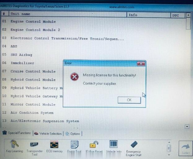
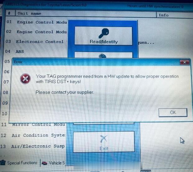
Solution:
Please try to solve this error by the following steps:
Step 1: Open the SVCI2020 installation directory
Step 2: Enter "C: Program Files (x86)\Abrites Commander Software List\Common2\†directory and copy Toyota folder to "C: Program Files (x86)\Abrites Commander Software List\Common\â€directory.
Posted by: obd2tool at
08:27 AM
| No Comments
| Add Comment
Post contains 92 words, total size 1 kb.
June 02, 2020
What should you do when the touch button at the bottom of your OBDSTAR X300 DP (primary key dp) no longer responds / does not work?
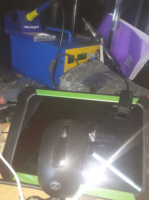
This is probably due to the chip overheating and burning out.
1) Replace the x300dp touch screen with a new one
2) Without this line, you can still use it. Use the physical button on the right.
3) Obtain a USB wireless mouse.
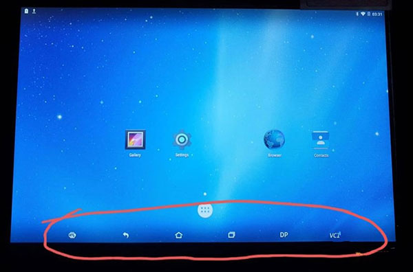
If you need a new screen (touch screen is $ 58, LCD screen is $ 110, excluding shipping), please contact us at sales@obd2tool.com.
Posted by: obd2tool at
08:15 AM
| No Comments
| Add Comment
Post contains 100 words, total size 1 kb.
Car model:
2005 F150 XLT
4.6L, 4wd
209k miles
Symptom:
Truck starts and drives. At idle no issues, temp comes up and at the
center temp mark the stat opens, recently installed a new stat and
radiator. Highway speed the temp gauge spikes to max and I get a message
to check gauges not warning lights and no limp mode. Pullover and idle
temp goes down, and stays down unless I get up to higher speeds again.
Nothing out of the ordinary with reservoir level, no mixing with oil.
Advice on how to do:
A device plugged into the OBDII which will display the temperature for
engine coolant, engine head, transmission fluid, etc. A lot of people
are downloading software online and buying an adapter. Some people buy
very expensive tools like shops and dealerships use.
You need to be able to read the truck’s computer. You want to see
what the temperature is for your coolant, and compare that with a point
and shoot thermometer.
When the needle on the dashboard is high, pull over and start checking
the temperature. Check the temperature at the cylinder head, thermostat,
and the hoses. See if the fan is turning on. Look at the water pump.
Vident ilink400

Reason:
It could be the water pump.
It could be just a bad sensor.
With this generation of trucks, the cooling system was not that complicated.
Thermostat opens to allow hot coolant out of the engine. If this does not work, the truck overheats.
Hot coolant travels through the upper radiator hose to the radiator. Airflow cools the fluid. At highway speeds, airflow is simply from your truck traveling so fast that air is flowing in through the grill. At lower speed, the cooling is assisted by the fan. Cool fluid goes back to the engine through the lower radiator hose. The water pump keeps this cycle going.
Since we know that at low speed, the truck is not overheating, we can believe that the thermostat is opening, the fan is working, and the water pump is doing it’s job. Now to figure out if the truck is actually overheating at highway speed. The needle on the dash is rising because the car’s computer is reading a high temperature signal. So check to see what temperature the computer is reading. Now check to see what the actual temperatures are. Your truck may not be overheating at all. If the water pump, fan clutch, or thermostat failed, you would overheat at low speed. While you are working on your cooling system, it doesn’t hurt to replace the belts & hoses, and pressure test the system. While you are at it, I would exchange the radiator fluid. Flush out the system and start with new coolant.
Credits to @Fifty150
Posted by: obd2tool at
08:00 AM
| No Comments
| Add Comment
Post contains 482 words, total size 4 kb.
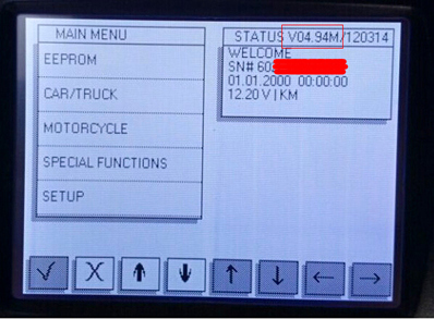
May 07, 2020
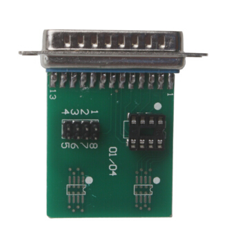
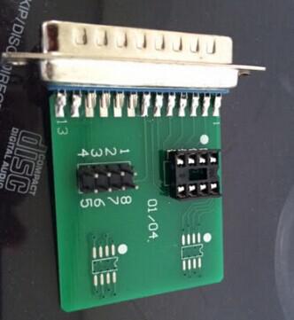
Here is the detail instruction on how to program EEPROM with Digiprog 3 v4.94 odometer correction tool through "EEPROM†menu.
EEPROM programming with Digiprog 3 is done through some adapters, for example, 01/04 Adapter,Digiprog 3 ST02 cable or others. These adapters can be purchased at local aftermarket shops or from online stores.
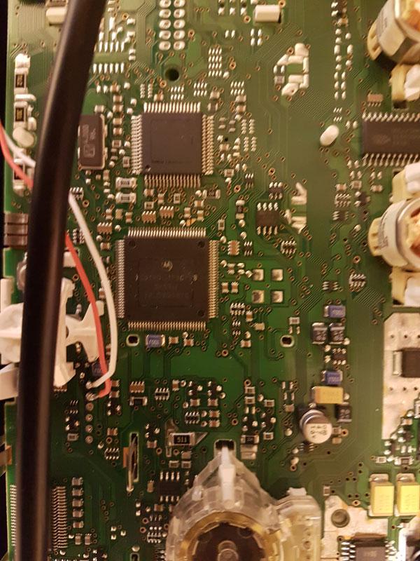
EEPROM chip 01/04 Adapter picture taken:
Tips before you start:
1. De-solder eeprom
2. Make sure the contact points or legs with glass fiber pin thoroughly.
3. Clean clearly with sandpaper, etc
4. Insert eeprom correctly into Digiprog3 ST01/ST04 adapter, and make sure they are contacting.
How to program EEPROM using digiprog 3 Mileage Correction Tool?
1. Connect DP3 device to your car via OBD connector
2. Enter "EEPROM†menu
3. Read data from EEPROM and store them in digiprog3
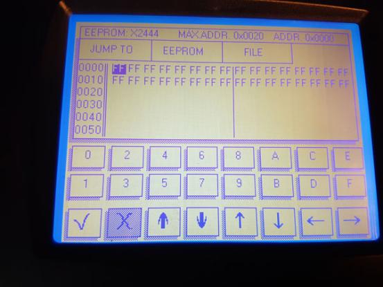
Follow this way:
Select the "SET TYPE†and choose "93C46″, then your digiprog has been
set up to read a 93C46 chip. Press "EEPROM†again and then "READâ€. There
will show you the information on the digiprog III screen when the
reading is complete. Now press "VERIFY†so the information on your
screen can agree with the Eeprom.
Next click the "FILE†and there will show you another sub-menu, you can
click "SAVE†and enter a file name for the information you are saving.
Once you entered the file name, your data is safe and the vehicle is now
ready to be reprogrammed.
4. Get EEPROM from ST01/ST04 adapter and reload it;
5. Select the function EEPROM COMPARE;
6. Then it is the previous read data on digiprog 3 but not the internal memory, comparing it with the now re-inserted EEPROM;
NOTE:
Error message may appear during the process, restore or reprogram, restore the original data status and it will be fixed.
External eeprom programmer
Read and store data status
Take EEPROM from the adapter and insert it again
Re-read data level and save it
Comparison on data sets in the editor (windows—total commander)
If the comparison is identical, it is correct.
If the data is restored already, the reprogramming error shows the original data
Data state produced!
Case: Digiprog3 read&write Audi A4 eeprom HC12 mileage
Purpose:
copy the immo information from a cluster to another
make the mileage follow with the immo information
Model:
Audi a4 2001
Optional devices:
Digiprog3, or ecu programmers like XPROG, Carprog, UPA-USB programmer
Original cluster:
The Jaeger cluster barely works

Suggestion:
read the pin code from both the Instrument and adapt it to the vehicle
What to do on pin 21 and 22 on the chip:
– With ECU programmers:
Eprom.set type,mcu,hc12,read,save.
eprom,set type,mcu,hc12,file,load,write.
Buy yourself Xprog-M, Carprog, UPA-USB.
Pin 21 and 22 jumper after programming or wait 10 minutes.
– with Digiprog3:
Eprom,set type,mcu,hc12,read,save.
eprom,set type,mcu,hc12,file,load,write.
Problem & Solution: Digiprog3 Can’t Read EEPROM
Problem:
Used OBD ST01 & ST04 cables (contained in Digiprog 3 entire kit)to read EEPROM. The pic below shows what I did.
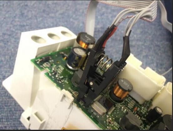
But the result can be seen like the following pic. The EEPROM cannot be read.
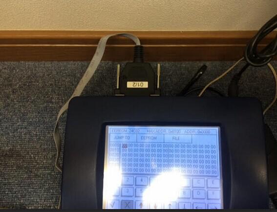
Solution:
Take down the clip and clear the chip. Then try it again.
If you do not want the clip,contact the purchasing specialist to ask for the 01/04 Adapter for Digiprog 3.
Disconnect digiprog 3 from your car when finished.
Posted by: obd2tool at
12:37 PM
| No Comments
| Add Comment
Post contains 548 words, total size 8 kb.
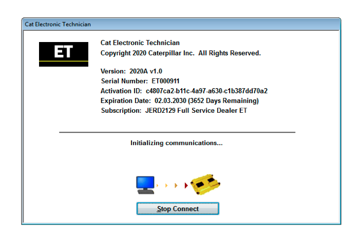
Caterpillar Electronic Technician (Cat ET) is diagnostic software required to communicate, diagnose, and service electronically controlled Caterpillar engines and machines when connected to an Electronic Control Module (ECM). It is possible to diagnose current and potential problems, product formation, and obtain data for analysis using this software.
The Caterpillar Electronic Technician Software works with the dealer diagnostic scanner Caterpillar Communication Adapter as well as other adapters for diagnostics, including scanner NEXIQ.
Cat ET features:
• Displays parameter status
• Displays active diagnostics
• Clear and View logged diagnostics
• Performs Diagnostic tests
• Print reports and diagnostic results
• Perform calibrations
• Uploads new software (Flash Files) to ECM’s
• Integration to help files
• Creates engine warranty reports
with this Version, you can choose license level :
Flash Technician Full Service
Flash Technician Factory
Flash Technician Internal
Caterpillar Product Data Transfer Utility – CPDTU
EERE3500 Military Cat ET
EERE3501 Licensed Military Cat ET
NEXG5076 Dealer Cat ET for Customer
MULT2129 Multi-Tool Full Service Dealer ET
Flash Technician Supplier
Flash Technician Flash Developer
EMDI0001 EMD Customer
CMIL3500 Cat ET for Canada Military
JERD2129 Full Service Dealer ET
JERD2142 Machines
JERD2129 Full Service Dealer ET
NEXG5006 Factory
JERD2141 Commercial Engines
NEXG5000 Tech School
JERD2125 On-Highway Truck ET
JERD2128 All Engines Combined (Truck and Commercial)
NEXG5050 Cat ET AGCO Subscription
EERE2001 Flash Factory Build
NEXG5009 On-Highway Truck Customer ET
NEXG5010 Ryder ET
NEXG5007 Full-Service Customer ET
NEXG5008 Internal
NEXG5035 Premium ET
EERE2001 Comet Factory Build
2020 PC Requirements
Region: All Regions
Languages: English, Chinese, Danish, French, German, Italian, Portuguese, Spanish
Operating System OS : Windows 10 , 8.1 8, 7, 32 bit (x86) & 64 bit (x64)
Download size 518 MB
Date of update: 03/2020
Posted by: obd2tool at
12:29 PM
| No Comments
| Add Comment
Post contains 292 words, total size 3 kb.
April 19, 2020
I’m going to swap my frm1 module with an frm2 module from 2008 so I can have the warm welcome halos light up when I unlock the car.
I finally got it in and working!
The angel eyes now turn on when I unlock the door, but I remember the
angel eyes slowly turning on when I tested it on the donor car.
On my car they just abruptly turn on.
Once your new frm module is in.
From the Ncs Expert MAIN MENU(once you open the app and connect to the car)
Click vehicle
Click vehicle order
Click CAS
Click Edit
Click date
Change date to March 2007
Click Actions
Click save
A window pops up, "choose locationâ€
Click both FRM and CAS.(it will change the date on both CAS and frm and copy your VO from CAS to FRM.
Once that’s done, your FRM should show the same VO as your BMW ICOM A2. If not, close the app and try again.
Default coding the FRM.
Main menu again:
Click safety
Click FRM(footwell module)
Click coding
Click default code
A window promoting you to make a back up will pop up, click confirm.
Click Car access system(CAS)
It will say "copying VO†then "codingâ€
It should say coding successful once it’s done.
Verify your new FRM has your vin written on it by clicking FUNCTIONS and then read vin(still in the frm menu).
If your vin is read, you’re done.
If Your FRM shows XXXXXXX as vin, relaunch the app and read the vin
again. If it still says XXXXXXX as vin, default code the frm again.
Really easy, should only take a few minutes.
Posted by: obd2tool at
08:31 AM
| No Comments
| Add Comment
Post contains 295 words, total size 2 kb.
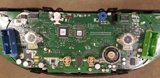
Model: 2016-2019 Lexus
Purpose: mileage correction
Ideal machine use and test reports:
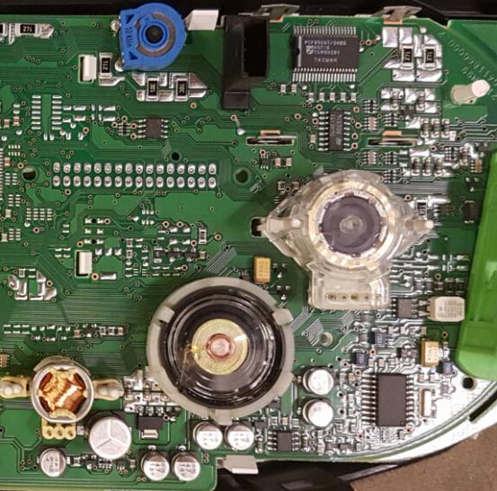
Dash has eeprom 93c86 … Very easy to calculate new miles.
Most eeprom programmers can read the chip. Unpack, unsolder, read and
post on the forum so someone can help you with calculations. No tool can
do this through obd port.
The safest way is to use a hex editor and a good programmer.
Any eeprom programmer, even yourDigiprog 3 can read … this is a simple 93c86 x 16-bit.
Yanhua Digimaster 3can correct mileage without any problems.
Carprog online dashboard odometer for Lexus 93C86 was successfully programmed.
Posted by: obd2tool at
08:18 AM
| No Comments
| Add Comment
Post contains 127 words, total size 2 kb.
April 08, 2020
Here, have collected the solutions for software operation problems from Xprog-M box ECU programmer users.
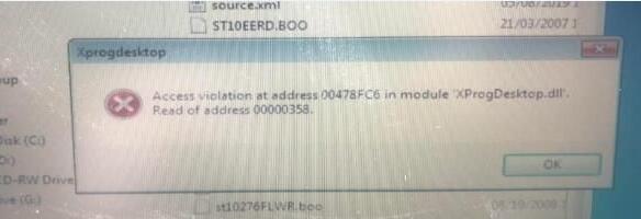
1. Problem: The xprog V5.84 shows "Access violation at address 00478FC6 in module "XProgDesktop.dllâ€. Read of address 00000358.â€
Solution: Check if the anti-virus software has been installed in the computer. If have, please close it, because the anti-virus software
will kill xprog-M driver. Then open the xprog V5.84 again. If it also doesn’t work, try to unzip xprog software again.
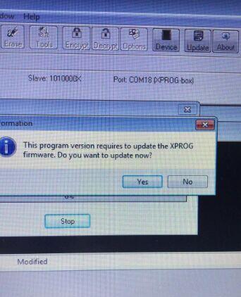
2. Problem: It always prompts "This program version requires to update the XPROG firmware. Do you want to update now?†when using xprog -M box.
Solution: Please check if you connect the internet, if it is, disconnect the internet. Never try to UPDATE, the hardware will be damaged if
you want to try to update it online, then you will lose its warranty.
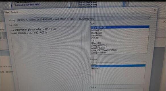
3. Problem: My Xprog V5.84 fail to read serial eeprom, don’t give eeprom options.
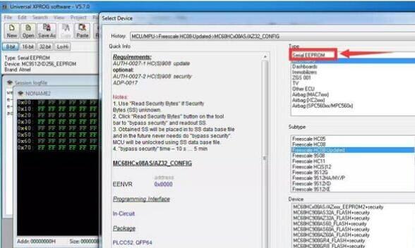
Error "For information, please refer to xprog-m users manualâ€.
Solution: Xprog v5.84 default software CD does not have eeprom capabilities which is different from previous version V5.74/5.60/5.55 etc.
But the new v5.84 software has modified the software to enable eeprom reading.
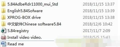
V5.84 new software free download link:
https://mega.nz/#!7vpDwQ4D!MrdDW0tVf-6-wXtGKqpUmj7CA2HFlFlMf5AeNvYgRbI
File contains:
Operating system: Windows XP/Windows 7/Windows 8
Language: English/Chinese
Tips for installing Xprog V5.84.
1).Disable anti-virus program when downloading software and running software.
2).Uninstall all the software and USB drivers of the old version xprog-box on your computer, then install the new XPROG5.84 software.
3).Run 5.84Regsisty program for several times when installing software
4).Run 5.84Regsisty file for 2 times before you run software every time .
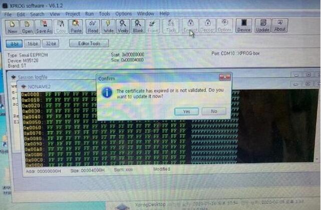
4. Problem: The certificate has expired or is not validated for Xprog V6.12.
Solution: There is no need to use xprog software by internet. If you connect the internet, it will prompt you to update the software as the
picture shown above. Once you update it online, the internet may damage Xprog hardware.
To be continued…
Posted by: obd2tool at
09:46 AM
| No Comments
| Add Comment
Post contains 330 words, total size 4 kb.
March 05, 2020
Yanhua ACDP now has changed the way of opening module authorizations. Customers can add the authorizations by yourself, very easy to operate.
Here is the steps:
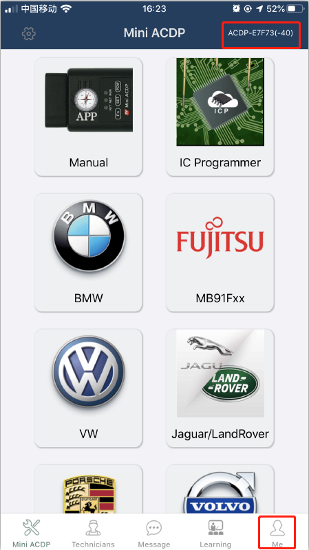
1.Bond the ACDP with mobile phone. After the ACDP bonded, it shows the device does not obtain the authorization of the relevant function, as shown:
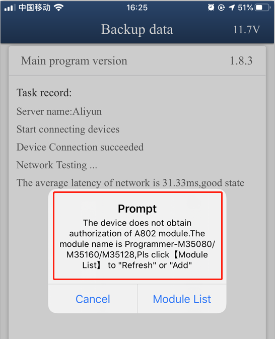
Notice: Please make sure the IOS version is 1.8.4 or above,and Android version is 3.0.92 or above.
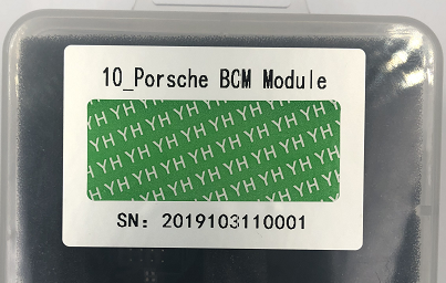
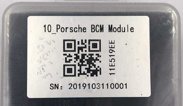
2. There is a paster with authorization code on the module box,take off the green security seal and clean up the QR code.
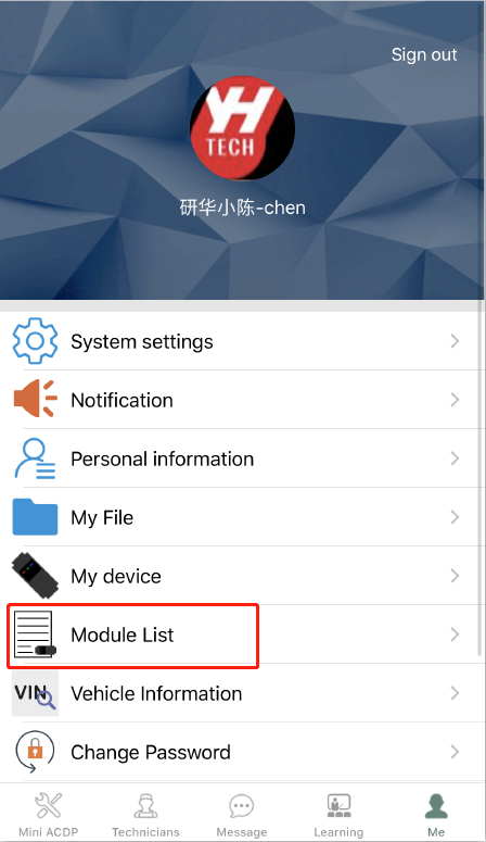
3.Make sure the ACDPAuto Key Programmer has bounded successfully,and click "meâ€ï¼š
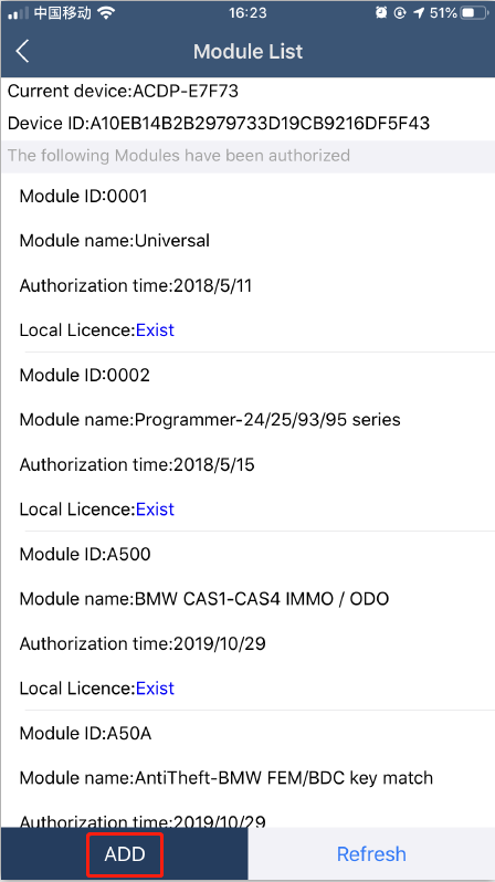
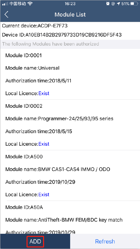
4. Click "module listâ€
5. Click "ADDâ€.
6. Click "Scan QR Code†to start scanning the QR code on the pasteror type the authorization card(Capital lettersonly).
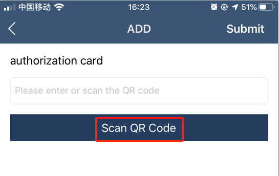
7. Check the authorization card number and click "Submit†after confirmed.
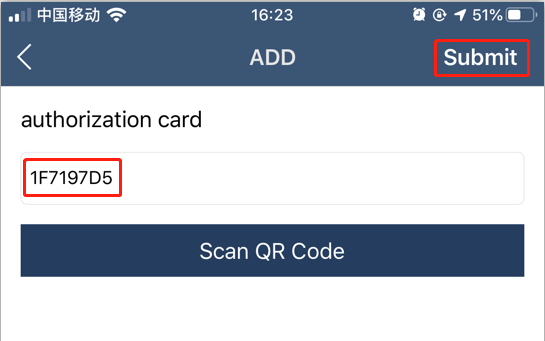
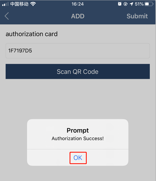
8. When the prompt comes with authorization success,click "OKâ€.
9. When the prompt comes with refreshing authorization info success,click "OKâ€.
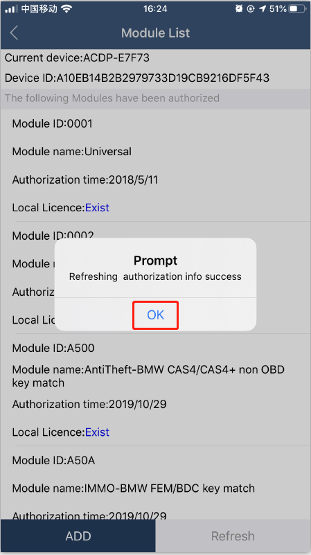
10. If you want more module authorization info,please click "ADDâ€for more.
11. If you change another phone or PC,after the ACDP bounded,please click "Refreshâ€to download your authorization info.
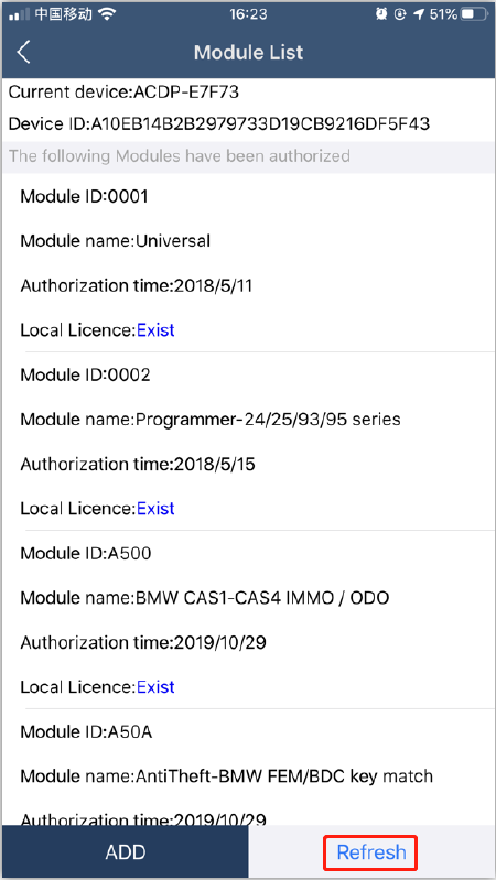
12. Finished.
Posted by: obd2tool at
10:02 AM
| No Comments
| Add Comment
Post contains 198 words, total size 6 kb.
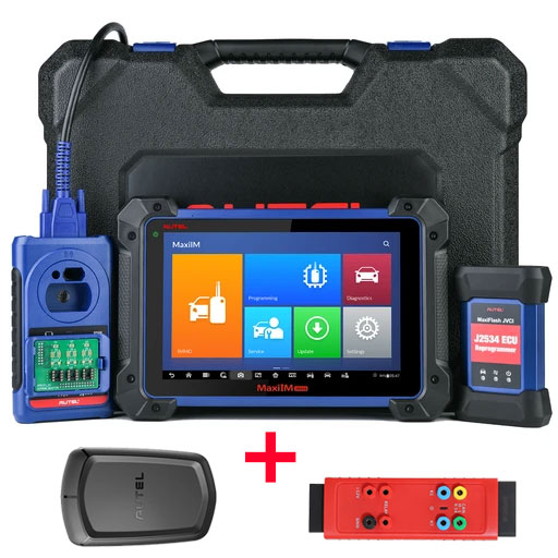
Here OBD2TOOL show you the guide on how to connect Autel IM608 programmer to vehicle.The IMMO operations require connecting the MaxiIM IM608 tablet to the test vehicle through the MaxiFlash using the main cable and the included USB cable (2m).
To establish proper vehicle communication to the tablet, you need to perform the following steps:
1.Connect the MaxiFlash to the vehicle’s DLC for both communication and power source.
2.Connect the MaxiFlash to the tablet via BT pairing, or USB connection.
3.When the above steps are completed, check the VCI navigation button at
the bottom bar on the screen, if a green check displays at the lower
right corner, theAutel Scanner MaxiIM IM608 is ready to start vehicle diagnosis.
Vehicle Connection
The method used to connect the MaxiFlash to a vehicle’s DLC depends on the vehicle’s configuration as follows:
A vehicle equipped with an On-board Diagnostics Two (OBD II) management
system supplies both communication and 12-volt power through a
standardized J-1962 DLC.
A vehicle not equipped with an OBD II management system supplies
communication through a DLC connection, and in some cases supplies
12-volt power through the cigarette lighter receptacle or a connection
to the vehicle battery.
OBD II Vehicle Connection
This type of connection only requires the main cable without any additional adapter.
To connect to an OBD II vehicle
1.Connect the main cable’s female adapter to the Vehicle Data Connector on the MaxiFlash, and tighten the captive screws.
2.Connect the cable’s 16-pin male adapter to the vehicle’s DLC, which is generally located under the vehicle dashboard.
NOTE
The vehicle’s DLC is not always located under the dashboard; refer to the user manual of the test vehicle for additional connection information.
Non-OBD II Vehicle Connection
This type of connection requires both the main cable and a required OBD I adapter for the specific vehicle being serviced.
There are three possible conditions for Non-OBD II vehicle connection:
DLC connection supplies both communication and power.
DLC connection supplies communication and power is to be supplied via the cigarette lighter connection.
DLC connection supplies communication and power is to be supplied via connection to the vehicle battery.
To connect to a Non-OBD II Vehicle
1.Connect the main cable’s female adapter to the Vehicle Data Connector on the MaxiFlash, and tighten the captive screws.
2.Locate the required OBD I adapter and connect its 16-pin jack to the main cable’s male adapter.
3.Connect the attached OBD I adapter to the vehicle’s DLC.
NOTE
Some adapters may have more than one adapter or may have test leads instead of an adapter. Whatever the case, make the proper connection to the vehicle’s DLC as required.
To connect the cigarette lighter
1.Plug the DC power connector of the cigarette lighter into the DC power supply input port on the device.
2.Connect the male connector of the cigarette lighter into the vehicle’s cigarette lighter receptacle.
NOTE
After the MaxiFlash is successfully connected to the vehicle, the Power LED on the device illuminates, and a brief beep sound will be heard.
VCI Connection
After the MaxiFlash is properly connected to the vehicle, the Power
LED on the MaxiFlash illuminates solid green, and is ready to establish
communication with the tablet.
The Wireless Diagnostic Interface supports two communication methods with the tablet: BT and USB.
Pairing Up via BT
Among all methods, BT pairing is recommended as the first choice for the communication between the tablet and the MaxiFlash. The working range for BT communication is about 210 feet (70 m); this means you can perform key programming and vehicle diagnosis freely around the workshop with greater convenience.
If you use more than one MaxiFlash to connect to the test vehicles when customers are many, you can perform key programming and vehicle diagnosis on various vehicles conveniently, by pairing the tablet separately to each of the MaxiFlash connected to the different test vehicles, via BT,without the need to repeat the plugging and unplugging procedure, which is unavoidable through traditional wired connection, thus saves you more time and provides more efficiency.
To pair up the tablet with the MaxiFlash via BT
1.If not already done, power up the tablet.
2.Select the VCI Manager application from the MaxiIM Job Menu.
3.When the VCI Manager application is opened, the device automatically
starts scanning for available VCI devices around for BT pairing. The
found devices are listed in the Setting section on the right side of the
screen.
NOTE
If no VCI device is found, this may indicate that the signal strength
of the transmitter is too weak to be detected. In this case try to get
closer to the device, or reposition the VCI device, and remove all
possible objects that may cause signal interference. When done, tap the
Scan button at the top right corner to start searching again.
4. The VCI device name displays as MaxiFlash suffixed with a serial number. Select the required device for pairing.
5. When pairing is successfully done, the connection status displayed to the right of the device name is shown as Paired.
6. Wait for a few seconds, and the VCI button on the system Navigation
bar at the bottom of the screen shall display a green check,indicating
the tablet is connected to the MaxiFlash, and is ready to perform
vehicle diagnosis.Refer to BT Pairing on page 126 for additional
information.
USB Cable Connection
The USB cable connection is a simple and quick way to establish
communication between the tablet and the MaxiFlash. After properly
connecting the USB cable from the tablet to the MaxiFlash, the VCI
navigation button at the bottom bar of the screen shows a green check in
a few seconds,and the USB LED on the MaxiFlash illuminates solid green,
indicating the connection between the devices is successful.
The MaxiIM IM608 tablet is now ready to perform key programming and vehicle diagnosis.
No Communication Message
If the tablet is not connected to the MaxiFlash, an "Error†message
displays. An "Error†message indicates the tablet is not communicating
with the MaxiFlash, and so cannot gain access to the vehicle control
module. In this case, you need to do the following check-ups:
Check if the MaxiFlash is powered on.
In case of wireless connection, check if the network is configured correctly, or if the right device has been paired.
If during the diagnosis process, communication is suddenly interrupted
due to the loss of signal, check if there are any objects that causes
signal interruption.
Check if the MaxiFlash is properly positioned. It is recommended to put the MaxiFlash with the front side up.
Try standing closer to the MaxiFlash to obtain more stable signals,and
faster communication speed. In case of wired connection, check the cable
connection between the tablet and the MaxiFlash.
Check if the green LED on the MaxiFlash is illuminated for BT or USB.
Check if the Error LED on the MaxiFlash is on, this may indicate there
is a communication error between the devices, in this case try
re-establishing the connection again; if this does not work, there may
be a hardware problem with the device, in this case contact Autel or
local distributor for technical support.
If the MaxiFlash is unable to establish a communication link, a prompt message displays with check instructions.
The following conditions are the possible causes for this massage to display:
The MaxiFlash is unable to establish a communication link with the vehicle.
You’ve selected a system for testing that the vehicle is not equipped with.
There is a loose connection.
There is a blown vehicle fuse.
There is a wiring fault on the vehicle, or the data cable or adapter.
There is a circuit fault in the data cable or adapter.
Incorrect vehicle identification was entered.
Posted by: obd2tool at
09:54 AM
| No Comments
| Add Comment
Post contains 1289 words, total size 10 kb.
February 24, 2020
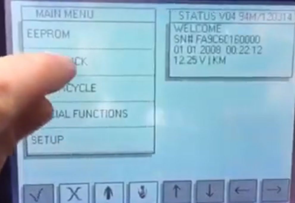
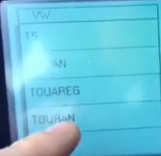
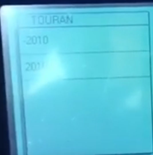
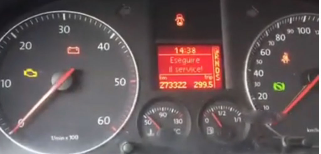
Here is the step-by-step tutorial of VW Touran odometer correction with Digiprog 3 v4.94 mileage programmer,
By OBD, Only in 1 5 minute.
Step1:Connect Digiprog iii with W211 via car OBD connector.
Power up Digiprog iii and you see notice information, just say yes.
Then enter password to open main menu.
Old mileage:273322km
Step 2:
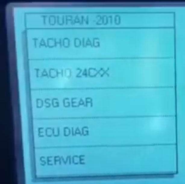
Select:COCHE/CARRO ->vw->TOURAN->-2010->TACHO->DIAGDigiprog3
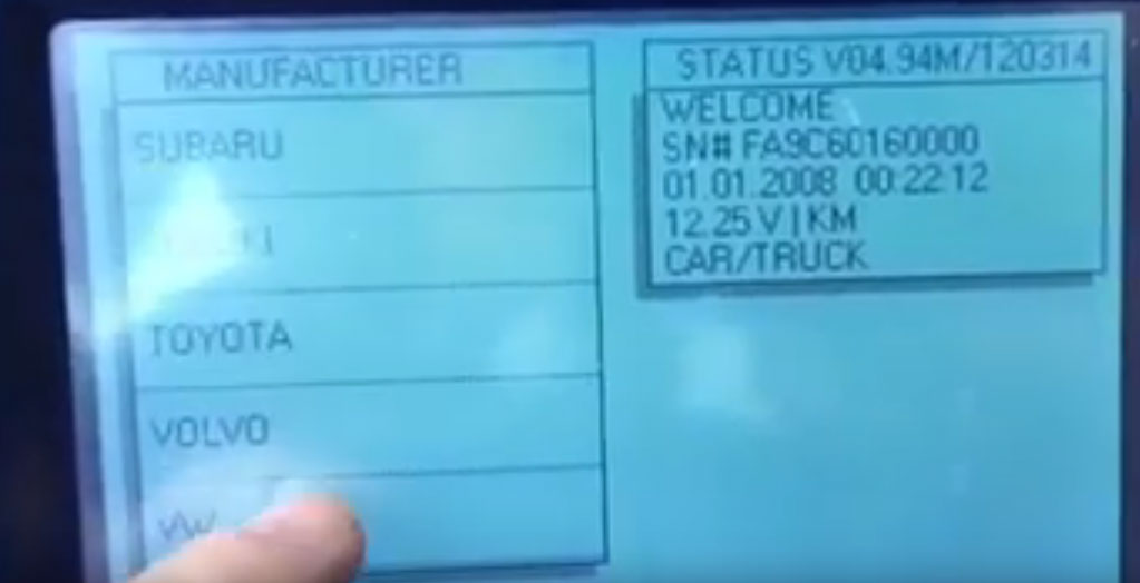
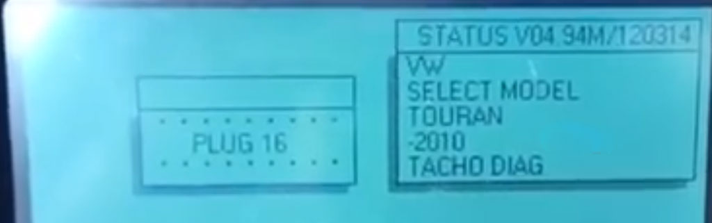
Now the centre control immobilizer indicator start blink. The Odometer Correction Tool Digiprog 3 read out the old odometer.
Enter new odometer value as 177696 and wait a while.
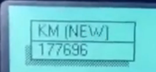
Change VW Touran mileage successfully by Digiprog 3 V4.94! Now new odometer value turn to 177696!
Posted by: obd2tool at
10:09 AM
| No Comments
| Add Comment
Post contains 111 words, total size 2 kb.
In this mini post,i will instruct how to do PDC-Acustic signal at first led coding by DTS Monaco software. And for DTS Monaco guide,you can check it here![]() TS Monaco Projects
TS Monaco Projects
Preparations:
Benz DTS Monaco Software Free Download
How to Install Mercedes Benz DTS Monaco Software
Procedures:
ECU![]() TS_212
TS_212
1.Choose PTS_212
2.Choose Konfiguration Tonausgabe
3.Change the desired options–>for signal at first led "permante tonausgabe front†& â€permanente Tonausgabe heckâ€
4.Click kodieren
5.Perfrom a hardreset
https://www.obd2tool.com/blog/2020/02/07/benz-dts-monaco-coding-for-pdc-acoustic-signal-at-first-led/
Posted by: obd2tool at
10:01 AM
| No Comments
| Add Comment
Post contains 83 words, total size 1 kb.
February 02, 2020
Recently, one customer got his new Key Programmer XTOOL X100 Pad2 but he is sad to find that this pad can’t work! He uses this pad2 to do BMW Key programming but fail. What happen? Let us find out why and solve this problem.
Here attach an image to express his situation:
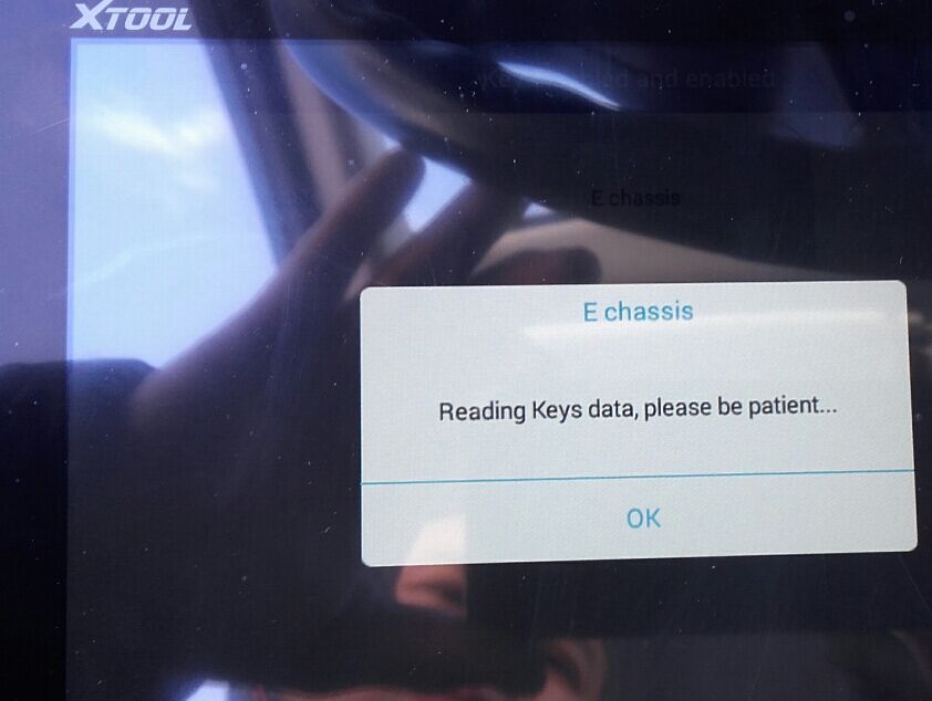
Customer: This weekend I tried a Q7 2006 to diagnose the pneumatic shock absorbers the aircraft supports only 5 marked so Jaguar, land rover, Benz and another brand. And my BMW 3 series E91 for DPF system (the fap) because I have the light FAP lit nothing it does not work.
Today I tried to program a key on a Golf 2000 gasoline and I can not, I try to make a BMW e46 it does not work either. I would like to have the procedure to follow !!! Please, thank you in advance
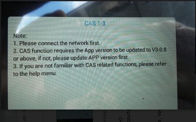
Engineer suggest customer change the menu from "F chassis and E chassis†to "CAS 1-3â€
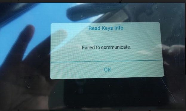
While customer still can’t do BMW key program after using the "CAS 1-3â€. And it appears a "Fail to communicate†and a CAS 1-3 using note:
Here are some tips to use XTOOL X100 Pad2:
* Choose the right menu or change the menu when you meet problem programming.
* Update the device to the latest version software.
* If the X100 Pad2 still can’t work after update, you could tap the
"Help†on the device to test the device so that the engineer could give
you more detail solution.
Posted by: obd2tool at
03:50 AM
| No Comments
| Add Comment
Post contains 264 words, total size 3 kb.
30 queries taking 6.7906 seconds, 178 records returned.
Powered by Minx 1.1.6c-pink.

